background image

Solid State Drive Optimization

13-169

Manually Running the Intel

®

SSD Optimizer

Note the following before manually running the Intel SSD Optimizer:

Do not run the Intel SSD Optimizer when a backup is in progress.

Do not run the Intel SSD Optimizer if the Intel SSDs are in a RAID configuration.

To run the Intel SSD Optimizer:

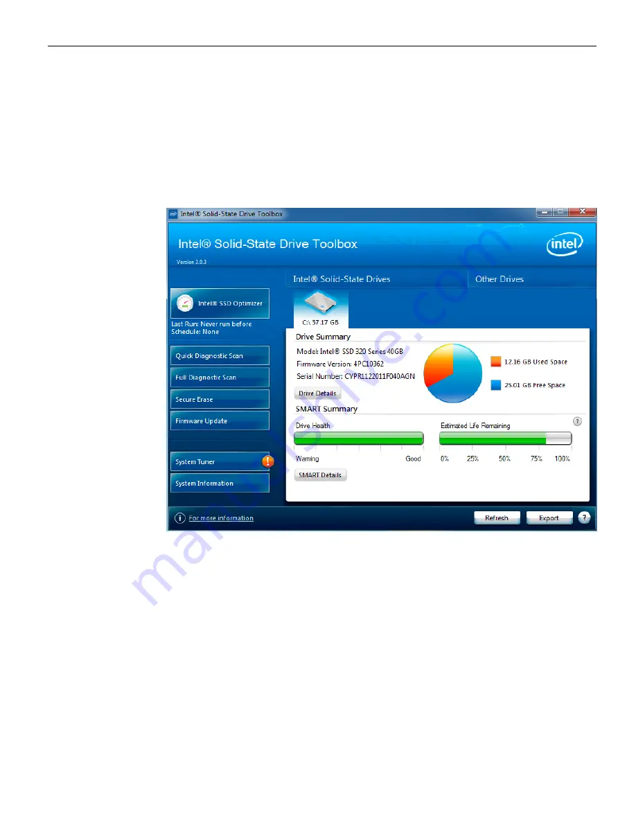
1. Click

Intel SSD Optimizer

.

Summary of Contents for RealPOS 72XRT POS

Page 1: ...USER GUIDE NCR RealPOS 72XRT POS 7616 Release 1 1 B005 0000 2228 Issue C...

Page 2: ...terms and conditions of an agreement you have with NCR NCR s copyright notice must be included It is the policy of NCR Corporation NCR to improve products as new technology components software and fi...

Page 3: ...AC power cord before opening the unit to install features or service this terminal Lithium Battery Warning Warning Danger of explosion if battery is incorrectly replaced Replace only with the same or...

Page 4: ...nded in accordance with all local codes and ordinances Do not modify the plug provided if it will not fit the outlet have the proper outlet installed by a qualified electrician Improper connection of...

Page 5: ...do not have access to a computer you may leave a voice message at 1 800 528 8658 USA or International 1 770 623 7400 When leaving a message please provide a phone number and or an email address so NC...

Page 6: ...ive equipment Equipment location in the store Description of the problem including any system error codes error condition or guidance to the area of failure The NCR Agent will provide you with a work...

Page 7: ...s 4 Display Wall Mount 7403 K321 6 Model and Serial Number Labels 7 Features 8 Key Features 8 Processor 8 Motherboard 8 Memory 8 Storage Options 8 Connectivity 9 Display 10 Consumer Display Options 10...

Page 8: ...action Printers 37 NCR RealPOS 7167 Printer 37 NCR RealPOS 7168 Printer 38 NCR RealPOS 7198 2ST Printer 39 Chapter 2 Installing the Terminal Introduction 41 Installation Summary 42 Installation Restri...

Page 9: ...h Screen Calibration Introduction 65 Installing the Driver 66 Touch Methods 67 Calibration Procedures 71 Verifying the Calibration 74 Optional Settings 75 Chapter 5 Configuring a Secondary Display Int...

Page 10: ...Connections 108 Powered USB Cable Connections 109 Installing an NCR 5975 5976 Remote Customer Display 110 USB Interface Powered 114 RS 232 Interface Powered 114 Installing a Cash Drawer 115 Installin...

Page 11: ...et Menu 147 Boot Menu 152 Chapter 11 BIOS Updating Procedure Introduction 153 Prerequisites 153 Creating a Bootable USB Drive 154 SPI BIOS Updating Procedures 154 Manually Updating the MAC Address 158...

Page 12: ...Chapter 14 Touch Screen Operation Introduction 181 Touch Mode of Operation 181 Changing the Touch Mode 182 Turning Off the Mouse Pointer 183 Terminal Placement 186 Chapter 15 Maintenance Cabinet and T...

Page 13: ...most demanding environments the NCR RealPOS 72XRT offers retailers in Hospitality Convenience Stores and General Merchandise a POS platform that offers exceptional value for their POS investment Prod...

Page 14: ...n variations This section illustrates each of these and lists the associated kits GMS Integration Tray Kit 7403 K300 This kit provides the necessary components for integrating a printer and keyboard w...

Page 15: ...ality Integration Tray Kit 7403 K301 This kit provides the necessary components for integrating a printer with the NCR RealPOS 72XRT terminal for a Hospitality environment It can be mounted on a flat...

Page 16: ...D and LCD customer displays on the back of the NCR RealPOS 72XRT terminal 7403 K451 Integrated 2x20 Customer Display 7403 K452 Rear Consumer Display Pole Mount for 5975 Display 7403 K453 Rear Consumer...

Page 17: ...Product Overview 1 5 There are four post options for the 5975 display available in 4 inch increments...

Page 18: ...1 6 Product Overview Display Wall Mount 7403 K321 This kit is used in to install a 7616 Display Head remotely on a vertical surface...

Page 19: ...del number labels located on the back of the Display Head on the top back edge of the Display Head and on the bottom of the Base If the terminal was shipped with an Operating System pre installed then...

Page 20: ...ovides tool free front access for service and upgrades Advanced systems management capabilities with Intel AMT Processor Intel G1610T processor 2 3Ghz Intel Core i3 3240T processor 2 9GHz Intel Core i...

Page 21: ...Connected through a cash drawer Kickout connector on the I O Board or through the cash drawer Kickout connector on the transaction printer The terminal can be configured with 0 1 or 2 cash drawers Th...

Page 22: ...mount All Points Addressable APA display 6 5 12 or 15 LED LCD display 15 Capacitive touchscreen Operating Systems Window 7 Professional Windows XP Professional Windows Embedded POSReady 7 Windows Emb...

Page 23: ...Product Overview 1 11 Lighted Logo to Indicate Power On Suspend Mode LAN Link Activity Hard Drive Activity Six Diagnostic LEDs...

Page 24: ...set supports 32GB 72XRT has 2 memory slots 4GB is largest memory module certified and released at this time 8GB 2 x 4GB Dynamic Video Memory Technology DVMT 5 0 Dynamic Video Memory Technology DVMT 5...

Page 25: ...e 3 5 250GB Option Dual SATA Hard Disk Drives Dual 2 5 250GB Option Solid State Drive SATA 2 5 40GB SSD Option Integrated Optical Drive Option SATA CD DVD ROM Option Onboard RAID support Standard 15 o...

Page 26: ...information to support ISO format cards The MSR is by default an OPOS device but can be reprogrammed for use with keyboard stream applications Note See the NCR MSR Configuration User Guide B005 0000 2...

Page 27: ...ar Signage Customer provided signage information 7 25 x 5 5 can be displayed on the back of the 7616 Plastic covers are required to hold the sign in place The Signage Kit 7403 K455 contains 5 plastic...

Page 28: ...move data or inject a virus via a USB port or other connection Some customers may prefer to keep a key attached to the terminal for service purposes The NCR RealPOS 72XRT provides a means to hide the...

Page 29: ...Product Overview 1 17 I O Board The I O Board is used to provide external connections for the motherboard It slides into position in the terminal below the motherboard...

Page 30: ...ying 24 V at 0 5 A continuous and 3 0 A peak A self healing Poly Fuse is used to provide current protection Serial Ports 4 RS 232 ports with selectable power 5 V 12 V or RI on pin 9 One RS 232 port is...

Page 31: ...Product Overview 1 19 Additional peripheral connectors are located under the Customer Display...

Page 32: ...ware or endangering service personnel The OS must be restarted to return to the Working state No hardware context is retained Except for the real time clock power consumption is zero G2 S5 Soft Off A...

Page 33: ...avings due to Intel s processor C states feature at nearly zero latency S2 Not supported S3 Suspend to Ram The S3 sleeping state is a low wake latency sleeping state This state is similar to the S1 sl...

Page 34: ...he system from entering S4 state S5 Unit OFF Reference the ACPI Specification for details Peripherals ACPI defines power states for peripherals which are separate from the system power state The devic...

Page 35: ...ght Off HDD Off Cache Flush Memory in Slow Refresh CPU Halted OFF Power Supply Status On On Powered Down Powered Down Powered Down Power Consumption 37 24 2 1 1 Wake Options Power Switch N A Y Y Y Y P...

Page 36: ...In order for Wake on LAN to function the Network driver must be enabled factory default The procedure for enabling the driver depends on which operating system you are using Windows 7 1 Select Start C...

Page 37: ...Product Overview 1 25 2 Expand Network adapters and then Right mouse click the Intel R 82567V Gigabit Network Connection driver Select Properties...

Page 38: ...6 Product Overview 3 Under the Power Management tab the Wake on Magic Packet and Wake on Magic Packet from power off state option boxes should be checked as shown below Select OK after making any chan...

Page 39: ...Product Overview 1 27 Windows XP 1 Select Start Control Panel Hardware Tab Device Manager button...

Page 40: ...1 28 Product Overview 2 Select Network adapters and then Right mouse click Intel R 82567V Gigabit Network Connection and select Properties...

Page 41: ...Product Overview 1 29 3 Under the Power Management tab the option boxes as shown below should be checked Select OK after making any changes...

Page 42: ...interfaces 5976 1100 2x20 LCD G11 5976 1200 2X20 LCD CG1 There are four post options available in 4 inch increments Features Display 2x20 Character Liquid Crystal Display LCD LCD Technology Advance B...

Page 43: ...nterfaces are active though only one interface can be physically connected at a time The display communicates via the interface that is connected to it Mounting Options Table Mount 4 in Post Table Mou...

Page 44: ...ion RGBW Rectangle LCD Backlit Technology LED Backlit Native Format 1024x768 262 144 colors RGB 6bits color depth or greater Viewing Direction 12 o clock 50K hour minimum backlight life at rated lumin...

Page 45: ...inch LCD Technology TFT Pixel Configuration RGBW Rectangle LCD Backlit Technology LED Backlit Native Format 1024x768 262 144 colors RGB 6bits color depth or greater Viewing Direction 12 o clock 50K h...

Page 46: ...LCD Backlit Technology LED Backlit Native Format 1024x768 262 144 colors RGB 6bits color depth or greater Display Mode Normally white Viewing Direction 12 o clock 370 cd m2 typ 300 cd m2 min luminance...

Page 47: ...lay Size 15 inch LCD Technology TFT Pixel Configuration RGBW Rectangle LCD Backlit Technology LED Backlit Native Format 1024x768 262 144 colors RGB 6bits color depth or greater 50K hour minimum backli...

Page 48: ...LCD Display The NCR 5982 LCD Display is a terminal powered color 6 5 Inch VGA LCD Features 5 inch VGA Monochrome LCD 640 x 480 VGA Contrast Control LED Back Light Keyboard Mount Low Post Table Top Mo...

Page 49: ...cks and prints on a variety of single or multiple part forms There is not journal as it is kept electronically by the host terminal The printer can connect through a USB port or a serial port It can r...

Page 50: ...RS 232C or USB communication interface The receipt station uses thermal printing technology Therefore there is no ribbon cassette to change and paper loading is extremely simple Printing on single or...

Page 51: ...ing on the receipt paper capability The printer can connect through a USB port or a serial port It can receive power from a power supply or through a USB power cable Features Print speed up to 52 line...

Page 52: ...1 40...

Page 53: ...http www info ncr com NCR Intranet http inforetail ncr com To locate the installation guides on these sites 1 Select General Search 2 Select the Kit Instructions icon 3 In the Kit Title field enter th...

Page 54: ...the terminal near an electrical outlet that is easily accessible Use the power cord as a power disconnect device Do not permit any object to rest on the power cord Do not locate the terminal where th...

Page 55: ...se Rear Cover This section shows how to gain access to the connectors and how to secure the cables VGA Extension Cable The VGA Extension Cable 1432 C327 0006 can be used to extend the VGA port from th...

Page 56: ...2 44 Installing the Terminal Accessing the I O Panel 1 Tilt the Display Module 2 Remove the Front Base Cover a Insert the Security Key and turn it 90 degrees clockwise...

Page 57: ...Installing the Terminal 2 45 b Pivot the top of the Front Base Cover toward the front of the unit and remove it from the terminal...

Page 58: ...A Max and is protected with self healing Poly Fuse The default setting for all four ports is Ring Indicator The 24 V printer and cash drawer circuits are also protected by a self healing Poly Fuse The...

Page 59: ...Installing the Terminal 2 47 Accessing the Backplane Connectors 1 Remove the screws 2 from the rear of the unit 2 Loosen the Captive Screws 2 and remove the Remote Display Base...

Page 60: ...2 48 Installing the Terminal AC Power Cord Connection 1 Connect the Power Cord to the system and to an AC power source 2 Secure the cable in the Cable Clamp...

Page 61: ...rminal 2 49 Cable Routing The cables from the I O Board are routed under the base and out the bottom of the unit Cables from the Backplane Board are routed out an opening in the Cover and down the bac...

Page 62: ...ard With DVD ROM Drive Without DVD ROM Drive Terminal Configured with a DVD ROM Drive If configured with a DVD the cables are routed in the two channels in the bottom of the Base Route the cables in t...

Page 63: ...erminal without a DVD ROM Drive If there is no DVD present then there is a Cable Clamp on the front of the Base chassis that is used to secure the cables 1 Loosen the Cable Clamp Thumbscrew 2 Pivot th...

Page 64: ...inal 3 Route the cable between the clamp and base 4 Route the cables in the two channels in the bottom of the Base as shown on the previous page and secure them with Tie Wraps as necessary 5 Secure th...

Page 65: ...outing from the Backplane Board 1 Remove the Remote Display Base 2 Connect the cable s to the Backplane Board 3 Route the cable s through the opening in the rear of the cabinet and down the back of th...

Page 66: ...onal VGA Extension Cable There is an optional short VGA Extension Cable that can be used to provide a VGA connection from the Backplane Board to the front of the terminal 1 Remove the Remote Display B...

Page 67: ...Terminal 2 55 3 Connect the VGA Extension Cable to the Backplane Board 4 Route the cable down the back and then under the terminal to the front 5 Locate the end of the cable in the area of the I O Bo...

Page 68: ...age Media options available for the 7616 Some devices are a large format 3 5 and some are a small format 2 5 Hard Disk Drive Large format Solid State Drive Dual Hard Disk Drive Small format used in RA...

Page 69: ...nit does not power on wait several more seconds and press the Terminal On Off Switch again Power Button Override When the Power Button is held for five seconds the system shuts down immediately This f...

Page 70: ...released or supported To request certification and support for third party devices submit your request through the Third Party Product website http www rsg ncr com tpp Keyboard support The RealPOS 72...

Page 71: ...component level A replacement component can be acquired by contacting the NCR Customer Satisfaction Hotline between the hours of 8AM and 5PM EST Monday Friday 1 800 528 8658 USA 770 623 7400 Internat...

Page 72: ...2 60...

Page 73: ...Chapter 3 POST Diagnostics Diagnostic LEDs The system power switch and a series of Diagnostic and Status LEDS are visible on the Front Base Cover...

Page 74: ...BIOS Checkpoint Description A B C Normal Operating condition after proper boot OFF OFF OFF D1 Keyboard Controller BAT test Check if waking from power management suspend state Save power on CPUID valu...

Page 75: ...mming successful 5 File read error 7 No Flash EPROM detected 10 Flash Erase error 11 Flash Program error 12 AMIBOOT ROM file size error 13 BIOS ROM image mismatch file layout does not match image pres...

Page 76: ...pe eliminate the possibility of interference by a malfunctioning add in card Remove all expansion cards o If Beep codes are generated when all other expansion cards are absent o If Beep codes are not...

Page 77: ...Calibration parameters are stored in the Windows registry and are unique for each touch screen therefore calibrate whenever an image or OS load occurs A keyboard may be required to start the calibrat...

Page 78: ...installation process 1 Extract the driver installation files into to a working directory on the POS terminal 2 Run the Setup exe program from this directory 3 Welcome screen Select Next 4 License Agre...

Page 79: ...anding that you normally expect to use the touch screen Touch the calibration target firmly and precisely with your fingertip During calibration be careful to keep your fingernails and other fingers a...

Page 80: ...4 68 Touch Screen Calibration Do NOT touch the display or bezel with your other hand Do NOT get your body too close to the display...

Page 81: ...Touch Screen Calibration 4 69 Do NOT touch the bezel with your other fingers Do NOT spread your other fingers near the touch screen surface...

Page 82: ...4 70 Touch Screen Calibration Do NOT get your hand and other fingers too close to the bezel...

Page 83: ...he terminal 45 degrees can be assumed if this not known If this was NOT done properly then begin with Step 1 Otherwise skip to Step 2 1 Select Start Programs Microchip TSHARC Control Panel Note The Ca...

Page 84: ...sage 6 Repeat the process for each target location as they appear 7 After all targets have been touched a test screen displays Touch the screen in various locations to verify the calibration results S...

Page 85: ...t touch the screen Caution Touching the screen during this time can cause the application to hang This screen automatically closes after the touch controller has completed communicating When complete...

Page 86: ...sely follow the underlying pattern Pay close attention to the edges of the display and the corners since this is where an incorrect calibration is most noticeable If a line or point appears to be outs...

Page 87: ...he other features to meet your personal preferences Double Click Option Right Mouse Click Touch Modes Touch Sounds 1 Touch the center of the target Pull your finger a few inches away from the screen w...

Page 88: ...ts If not select Cancel and repeat the process Note Do not touch ESC to exit from this screen 4 After touching Accept you are warned to not touch the screen Caution Touching the screen during this tim...

Page 89: ...onitor port VGA on the Backplane connector row These two ports can provide either a single display mode Notebook or Monitor or a dual display mode Notebook and Monitor Dual display mode can be a clone...

Page 90: ...hat are connected to the Motherboard ports The dual mode is configured with the Intel Graphics and Media Control Panel Right click the Desktop From the menu select Graphics Properties to display the p...

Page 91: ...Configuration Mode Description Single Display Single display even if two displays are connected Clone Displays Drives both displays with the same video content Extended Desktop Drives the both display...

Page 92: ...h unknown results on the other or be software accelerated A full screen command prompt or MS DOS application will only function on the Primary Device Intel Graphics Controller Hot Keys Hot Keys provid...

Page 93: ...on Compliancy Project Version Build Date and Time Customer Reference Number Memory Information Total Memory System Language System Date System Time Access Level SMBIOS Information Manufacturer Product...

Page 94: ...ng CPU Configuration SATA Configuration Thermal Configuration ASF Configuration Acoustic Management Configuration HDD S M A R T Status Intel ID SESCI OpRegion Intel TXT LT Configuration USB Configurat...

Page 95: ...sabled Enabled AMT Parameters ___________________ Select Screen Click Select Item Enter Dbl Click Select Change Opt F1 General Help F2 Previous Values F9 Load Defaults F10 Save and Exit ESC Right Clic...

Page 96: ...Intel R Standard Manageability Configuration Exit Intel R ME Password ESC Exit ENTER Submit 9 Enter the new password write it down to remember The password must contain upper lower symbol numeric cha...

Page 97: ...bility Configuration Exit ESC Exit Select ENTER Access ESC Exit ENTER Submit 11 Highlight Activate Network Access and press Enter Intel R Management Engine BIOS Extension v7 0 0 0056 Intel R ME v7 1 2...

Page 98: ...hts Reserved MAIN MENU Manageability Feature Selection SOL IDER User Consent Password Policy Network Setup Activate Network Access Unconfigure Network Access Remote Setup and Configuration ESC Exit Se...

Page 99: ...er ipconfig and press Enter The IP address is displayed Linux Switch Focus to the Instructions window Enter ipconfig and press Enter The IP address Inet adder is displayed 2 Open the browser on the PC...

Page 100: ...6 88 Configuring AMT 5 Enter the UserName and Password and then select OK UserName admin Password your password...

Page 101: ...Configuring AMT 6 89 The System Status Screen is displayed You can now control the AMT functions...

Page 102: ...displayed Processor Displays the CPU information from DMI Memory Displays the Memory information from DMI for each Bank when populated including the memory manufacturer Disk Displays the Disk informa...

Page 103: ...Power Policies Used to change the Power Policy remotely Network Settings Displays the AMT computer name and DHCP static IP addresses Wireless Settings Not Applicable User Accounts Used to create diff...

Page 104: ...6 92...

Page 105: ...ional remote peripheral devices Cable Routing Peripheral cables connect to the I O Panel behind the Base Front Cover or to the Backplane Board See the Connecting the External Cables section in the Ins...

Page 106: ...ys See the GMS Integration Tray 7616 K300 or Hospitality Integration Tray 7616 K301 Kit Installations for more information The printers can connect through a USB connector or an RS 232 connector It re...

Page 107: ...from Powered USB 1 Connect the RS 232 Printer Interface Cable to the RS 232 connector on the printer and to an RS 232 connector on the terminal 2 Connect the Printer Power Cable to the Power connecto...

Page 108: ...RealPOS 5943 12 1 Inch Monitor NCR RealPOS 5943 15 Inch Monitor NCR RealPOS 5967 12 1 Inch Touch Monitor NCR RealPOS 5967 15 Inch Touch Monitor The displays are installed on the mount in a similar fas...

Page 109: ...Installing Optional Remote Peripherals 7 97 2 Route the cable s down through the mount and out the back of the base 3 Connect the cable to the proper connector on the host terminal...

Page 110: ...NCR RealPOS 5943 12 inch LCD Cable Connections The following illustrations show the cable connections for the 5943 LCD and the 7616 terminal There are two cables required VGA cable for video Powered...

Page 111: ...Installing Optional Remote Peripherals 7 99 VGA Connections Connect the LCD Cable to the VGA connectors on both the 5943 LCD and 7616 terminal...

Page 112: ...erals Powered USB Cable Connections Connect the Powered USB Cable to the 5943 LCD and to one of the 12V Powered USB connectors on the 7616 terminal For more information refer to the NCR RealPOS 5943 1...

Page 113: ...NCR RealPOS 5943 15 inch LCD Cable Connections The following illustrations show the cable connections for the 5943 LCD and the 7616 terminal There are two cables required VGA cable for video Powered...

Page 114: ...7 102 Installing Optional Remote Peripherals VGA Connections Connect the LCD Cable to the VGA connectors on both the 5943 LCD and 7616 terminal...

Page 115: ...7 103 Powered USB Cable Connections Connect the Powered USB Cable to the 5943 LCD and to one of the 12V Powered USB connectors on the 7616 terminal For more information refer to the NCR RealPOS 5943 1...

Page 116: ...R RealPOS 5967 12 inch Touch LCD Cable Connections The following illustrations show the cable connections for the 5967 LCD and the 7616 terminal There are two cables required VGA cable for video Power...

Page 117: ...Installing Optional Remote Peripherals 7 105 VGA Connections Connect the LCD Cable to the VGA connectors on both the 5967 LCD and 7616 terminal...

Page 118: ...ls Powered USB Cable Connections Connect the Powered USB Cable to the 5967 LCD and to one of the 12V Powered USB connectors on the 7616 terminal For more information refer to the NCR RealPOS 5943 12 I...

Page 119: ...R RealPOS 5967 15 inch Touch LCD Cable Connections The following illustrations show the cable connections for the 5967 LCD and the 7616 terminal There are two cables required VGA cable for video Power...

Page 120: ...7 108 Installing Optional Remote Peripherals VGA Connections Connect the LCD Cable to the VGA connectors on both the 5967 LCD and 7616 terminal...

Page 121: ...09 Powered USB Cable Connections Connect the Powered USB Cable to the 5967 LCD and to one of the 12V Powered USB connectors on the 7616 terminal For more information refer to the NCR RealPOS 5943 15 I...

Page 122: ...10 Installing Optional Remote Peripherals Installing an NCR 5975 5976 Remote Customer Display There are two models of the NCR 5975 5976 Remote Customer Displays 5976 1xxx 2x20 VFD 5975 2xxx Graphical...

Page 123: ...4 meters 13 ft of the host terminal 2 Determine if the cable should be routed down through the mounting surface or if it should be run on top of the surface Drill a hole if necessary 3 If you are inst...

Page 124: ...als a Remove the screws 2 from the Display Back b Remove the Display Back c Route the Interface Cable though the opening in the Display Back d Connect the cable to the proper connector on the Display...

Page 125: ...ling Optional Remote Peripherals 7 113 5 Route the Interface Cable through the Post and assemble the Post components 6 Connect the Display Cable to the terminal based on the type of interface you are...

Page 126: ...d Connect the I F cable to a powered RS 232 connector on the terminal Note The factory settings for the COM ports are non powered by default To change a port to powered see the Circuit Boards chapter...

Page 127: ...Installing Optional Remote Peripherals 7 115 Installing a Cash Drawer The Cash Drawer can be connected to the Cash Drawer connector or to the transaction printer...

Page 128: ...minal also supports a 2 drawer configuration using a Y cable 1416 C372 0006 connected to terminal or to the printer 1 Place the cash drawer in the desired location within cable s length of the printer...

Page 129: ...can have additional protection against data loss in the event of hard drive failure Valuable digital memories are protected against a hard drive failure when the system is configured for one of the fa...

Page 130: ...imary HDD 2 Load the NCR Gold Drive 3 Install the second hard disk drive in the terminal hot plug 4 Run the Intel Rapid Storage Technology Manager Start All Programs Intel Intel Rapid Storage Technolo...

Page 131: ...ports RAID 1 and RAID 0 volume types RAID 1 Combines two disks to create a volume where each disk stores an exact copy of the data and provides real time redundancy RAID 0 Combines two disks to create...

Page 132: ...ct the check boxes for both disks RAID 0 Only Specify the amount of space to be used by the new RAID volume Use the slider to enter a percentage Note If you create a volume that uses less than 100 of...

Page 133: ...Configuring a Second HDD for RAID 8 121 10 Select Next 11 Select Create Volume to start the volume migration 12 Select OK to confirm the action...

Page 134: ...Second HDD for RAID 13 A window is displayed indicating the volume was created successfully Select OK to close the window The status of the migration is displayed showing the progress This can take 1...

Page 135: ...ded or Rebuild status You are advised to press CTRL I to enter the Configuration Utility to correct the condition This procedure is not recommended because of the possibility of inadvertently destroyi...

Page 136: ...cedure 1 Replace the defective HDD hot plug 2 Run the Intel Rapid Storage Technology Manager Start All Programs Intel Intel Rapid Storage Technology 3 The Status screen indicates the failed disk Selec...

Page 137: ...Configuring a Second HDD for RAID 8 125 5 The status of the disk rebuild is displayed showing the progress This can take 1 3 hours to complete...

Page 138: ...8 126...

Page 139: ...ral Specifications Item Value Number of characters 2 Rows x 20 Characters Character Configuration 5 x 8 Character Height 8 86 mm Character Width 3 90 mm Character Pitch 5 15 mm Line pitch 9 64 mm Peak...

Page 140: ...e the character D1 through D40 represent the character dots A 1 indicates the dot is on and 0 indicates the dot is off in the following format 5 x 8 Dot Matrix Character D1 D2 D3 D4 D5 D6 D7 D8 D9 D10...

Page 141: ...splay the character of the new table After a reset the character table is set to Table 1 Table Code Character Table 01h Table 1 02h Table 2 03h Table 3 04h Table 4 Clear Display 12h This command sets...

Page 142: ...s ignored if the POSITION byte value is greater than 27h This command resets the module to the following conditions 1 2 3 4 5 6 7 8 9 10 11 12 13 14 15 16 17 18 19 20 1 00h 01h 02h 03h 04h 05h 06h 07h...

Page 143: ...haracter data This character is written to the current cursor position and the cursor position is then incremented by one When data is written to the last character position of the top line the cursor...

Page 144: ...9 132 2x20 Customer Display Interface CP437...

Page 145: ...2x20 Customer Display Interface 9 133 CP858...

Page 146: ...9 134 2x20 Customer Display Interface CP866...

Page 147: ...2x20 Customer Display Interface 9 135 CP932...

Page 148: ...9 136...

Page 149: ...F1 To save the changes move the cursor to the Exit Menu select either Save Changes Exit or Save Changes and press Enter Restoring Factory Settings To reset all values to their default settings for th...

Page 150: ...1 2 5 Notes 1 This keystroke can be configured to be a different value based on the system manufacturer s specification The keystroke listed here is the default setting in AMIBIOS8 2 This feature is n...

Page 151: ...nitialization also known as boot block code To initiate these functions please hold down the keys immediately after powering on the system 8 After AMIBIOS recognizes this keystroke the BIOS will wait...

Page 152: ...y EFI Compatible ROM PCIbit Resources Handling Above 4G Decoding Disabled PCI Common Settings PCI Latency Timer 32 PCI Bus Clocks VGA Palette Snoop Disabled PERR Generation Disabled SERR Generation Di...

Page 153: ...Computing TPM Configuration TPM Support Enabled CPU Configuration Hyper threading Enabled Active Processor Cores All Limit CPUID Maximum Disabled Execute Disable Bit Enabled Intel Virtualization Techn...

Page 154: ...y 2 Seconds Serial SATA Port 0 ST250LT003 9YG 250 0 variable Software Preserve SUPPORTED Port 0 Enabled Hot Plug Enabled Mechanical Presence Switch Disabled External SATA Disabled SATA Device Type Har...

Page 155: ...esence Switch Disabled External SATA Disabled SATA Device Type Disabled Spin Up Device Disabled ASF Configuration ASF Support Enabled AMT Configuration Intel AMT Disabled WatchDog Disabled HDD S M A R...

Page 156: ...o Report Configuration Summary Screen Disabled SMART Settings Smart Self Test Disabled System Super IO Configuration Serial Port 1 A Configuration Serial Port Enabled I O Base Address 0x3F8 IRQ IRQ4 D...

Page 157: ...allel Port Disabled H W Monitor Smart Fan Mode Automatic Mode Fan OFF temperature limit 10 Fan Start temperature limit 35 Fan Start PWM 50 PWM Slope 2 PWM Temperatures Speeds Voltages Typical Acceptab...

Page 158: ...nsole Redirection Disabled Settings If Enabled Out of Band Mgmt Port COM0 Disabled Terminal Type VT UTF8 Bits per second 115200 Flow Control None Data Bits 8 Parity None Stop Bits 1 CPU PPM Configurat...

Page 159: ...ed Subtractive Decode Disabled PCI Express Root Port 1 2 4 5 6 ASPM Support Auto URR Disabled FER Disabled NFER Disabled CER Disabled CTO Disabled SEFE Disabled PMI SCI Enabled Hot Plug Disabled PCIe...

Page 160: ...Disabled Azalia PMI Disabled Azalia Internal HDMI Codec Disabled BIOS Security Configuration SMI Lock Disabled BIOS Lock Disabled GPIO Lock Disabled BIOS Interface Lock Enabled RTC RAM Lock Enabled PC...

Page 161: ...DVM Pre Allocated 64MB DVMT Total Gfx Mem 256MB Gfx Low Power Mode Enabled Graphics Performance Analyzers Disabled LCD Control Primary IGFX Boot Display VBIOS Default LCD Panel Type VBIOS Default SDVO...

Page 162: ...e PEG Auto De emphasis Control 3 5 dB PEG Sampler Calibrate Auto Swing Control Enabled Gen3 Equalization Enabled Gen3 Eq Phase 2 Auto PEG Gen3 Root Port Preset Value Lane 0 15 8 PEG Gen3 Endpoint Pres...

Page 163: ...Down Mode PPD Scrambler Seed Generation Off Disabled Memory Remap Enabled Memory Alias Check Disabled Channel A DIMM Control Enable Both DIMMs Channel B DIMM Control Enable Both DIMMs Memory thermal...

Page 164: ...essages Force BIOS Interrupt 19 Capture Disabled CSM Support Enabled Set Boot Priority 1st Boot Network I BA GE Slo 2nd Boot CD DVD 3rd Boot Hard Disk Intel Vo 4th Boot USB CD DVD 5th Boot USB Hard Di...

Page 165: ...CR Retail Systems Manager RSM Software User s Guide B005 0000 1518 for information about this procedure Prerequisites The following are required to perform a SPI BIOS update USB Keyboard BIOS Software...

Page 166: ...re effective Syslinux sfma USB drive letter Important Do not run syslinux by double clicking on it because it may affect the boot drive of the terminal being used to create the drive Windows 7 Note Th...

Page 167: ...displayed during power up Press Tab at the NCR Logo to remove the logo Press Pause to freeze the screen Press Esc to continue 5 Make a menu selection and follow the screen prompts Option 1 is recommen...

Page 168: ...1 Highlight Option 3 and press ENTER 2 At the prompt press ENTER to enter the Class Model Serial Number information DMI Follow the onscreen format instructions Example 7616 1500 8801 ENTER 54 19378230...

Page 169: ...enter the Class Model Serial Number information DMI Follow the onscreen format instructions Example 7616 1500 8801 ENTER 54 19378230 ENTER 3 Press 1 to confirm the data and to continue 4 The Flash Pr...

Page 170: ...data Forced Update of Serial Model Class Information 3 Update DMI only Serial Model Class update ONLY no BIOS SPI Update Only one boot no need for AC Power removal 4 Update of SPI and BIOS Always prom...

Page 171: ...ery from a CD Bootable CD DVD ROM drive Keyboard Procedures for Windows XP Pro POSReady 2009 1 Insert the NCR Partition Image Application CD D370 0605 0100 into the CD DVD drive 2 Connect a keyboard t...

Page 172: ...Storage A Size 250GB 3 Directory path is Images 4 Filename is nnnnnaaa 5 Reboot after operation complete yes 6 Resize last data partition if possible no 7 Resize last data partition to Full Disk 8 Wri...

Page 173: ...onfiguration before performing the OS recovery After recovering the primary disk you can then re configure the RAID 1 Connect a keyboard to the terminal 2 Insert the imaging utility DVD into the DVD d...

Page 174: ...erating System Recovery 8 Select the destination where the image should be deployed from the drop down menu Also select the radio button to reboot the terminal after the image has been installed Selec...

Page 175: ...ge is deployed a progress bar indicates the status 10 After the image has been put on to your terminal you are given the message Press OK to Reboot Select OK 11 Remove the DVD before the system reboot...

Page 176: ...12 164...

Page 177: ...n allows the SSD to clean up internal management space thus eliminating the need to manage the deleted files You can schedule the Intel SSD Optimizer to run automatically on a weekly daily or monthly...

Page 178: ...ion 8 x or Intel Rapid Storage Technology Intel RST Driver Version 9 5 or Earlier If your computer uses this configuration which can be used in place of the Microsoft AHCI driver Trim functionality is...

Page 179: ...w intel com go ssdtoolbox 2 Save the Intel SSD Toolbox application exe file to your computer 3 Double click the downloaded exe file to start the Intel SSD Toolbox setup wizard 4 Select a language from...

Page 180: ...ayed The Intel SSD Toolbox home screen shows all Intel Solid State Drives and hard disk drives installed in your system Click on the drive you want to manage If your system contains multiple drives us...

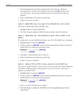
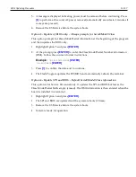
Page 181: ...zer Note the following before manually running the Intel SSD Optimizer Do not run the Intel SSD Optimizer when a backup is in progress Do not run the Intel SSD Optimizer if the Intel SSDs are in a RAI...

Page 182: ...13 170 Solid State Drive Optimization 2 Click Run 3 Review the text describing the Intel SSD Optimizer requirements and then click Start...

Page 183: ...t in a RAID configuration but is encrypted click Accept to continue running the Intel SSD Optimizer on the selected SSD If the Intel SSD is in a RAID configuration click Decline to stop running the In...

Page 184: ...to run a scheduled session Do not schedule the Intel SSD Optimizer to run when a backup is in session Do not run the Intel SSD Optimizer if the Intel SSDs are in a RAID configuration To schedule the I...

Page 185: ...Solid State Drive Optimization 13 173 4 Click Schedule If your computer contains more than one Intel SSD you can apply the schedule to all supported Intel SSDs by clicking All Supported Intel SSDs...

Page 186: ...13 174 Solid State Drive Optimization 5 Set the schedule including day time and frequency 6 Click Add 7 Review the requirement text and click Schedule...

Page 187: ...to continue running the Intel SSD Optimizer on the selected SSD If the Intel SSD is in a RAID configuration click Decline to stop running the Intel SSD Optimizer The Intel SSD Optimizer cannot run on...

Page 188: ...ick IntelSSD Optimizer 2 Click Schedule 3 Click Remove next to the schedule you want to delete Additional Information For additional information about SSDs go to www intel com go ssd The Intel SSD Too...

Page 189: ...on SSDs formatted with the FAT32 file system New Technology File System NTFS is required to run Intel SSD Optimizer NTFS allocation sizes of 32K and 64K are not supported Systems in IDE mode Intel SSD...

Page 190: ...configuration are recognized by Intel SSD Toolbox Not all drives in a RAID configuration are recognized by Intel SSD Toolbox Drive details and SMART information may be obtained with another program In...

Page 191: ...tions with allocation sizes of 32K or 64K the Intel SSD Optimizer fails to complete and leaves temporary files on the target SSD There is no workaround for this issue however if this occurs consider r...

Page 192: ...13 180...

Page 193: ...is made when the item on the screen is touched and activated when double touched Multiple items can be selected by touching and dragging your finger to another location forming a rectangular box to en...

Page 194: ...he Touch Mode The default touch mode setting is Normal You can switch modes in the Windows Control Panel 1 Select Start Programs Microchip TSHARC Control Panel 2 Select the Touch Settings tab 3 Select...

Page 195: ...At this site select the Support tab b Select Drivers and Patches Retail Support Files NCR RealPOS and SelfServ Terminal and Operating Systems NCR RealPOS 72XRT 7616 Windows Windows XP Pro Windows EP E...

Page 196: ...14 184 Touch Screen Operation 6 Select Normal Select from the Customize list 7 Select Browse 8 Navigate to the empty cur file...

Page 197: ...Touch Screen Operation 14 185 9 Select Open Apply The pointer should now be changed to none in the Mouse Properties Note To change back to the original settings select Use Default Apply OK...

Page 198: ...ls are installed within 254 mm 10 in of each other it may be necessary to change the touch operating frequency on one or more of the units to prevent interference when they are operated simultaneously...

Page 199: ...side the unit If liquid does get inside have a qualified service technician check it before you power it on again 6 Remove vacuum extra dust from around the cooling vents See Cooling Vent Cleaning sec...

Page 200: ...should be cleaned periodically to maintain optimum cooling for the CPU Procedure 1 Shut the system down and disconnect the AC power cord 2 Use the hose attachment on a standard household vacuum clean...

Page 201: ...trostatic Discharge ESD which can cause failures when swiping cards that have metallic hologram stripes Swipe the card through the MSR in a smooth motion Only swipe it down ONCE and up ONCE Allow the...

Page 202: ...an MSR Cleaning Card before treating it with a MSR Treatment Card For low use retail establishments the cleaning and treatment procedures should be followed at least once per month In areas of extreme...

Reviews: