NCR RealScan 7892 Bi-Modal Presentation Scanner Installation and Owner Guide
04/03
497-0003071 Release E
8 of 38
Dongle Interface Setting
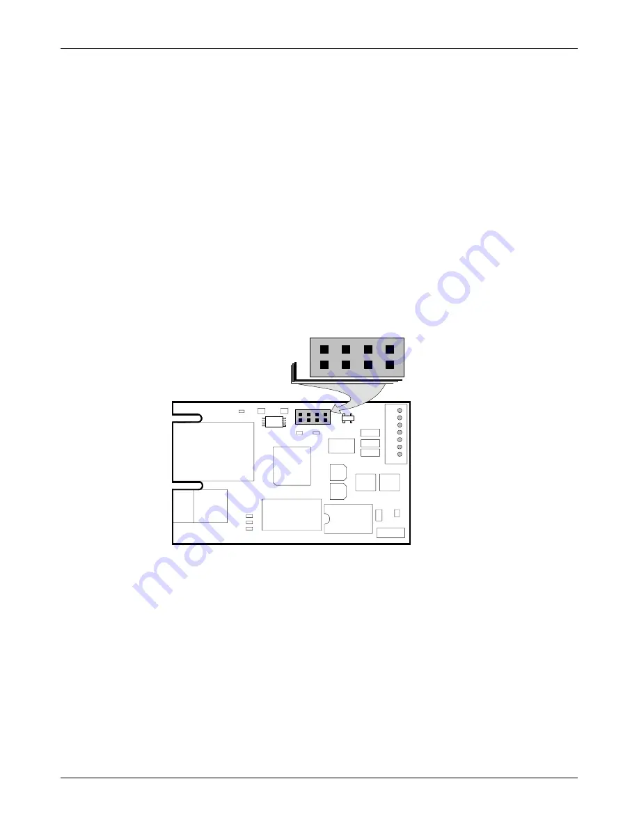
J3 in the Interface Box on the end of the Dongle Adapter Cable contains a shunt that
must be correctly installed for the host terminal. The cable is shipped from the factory
with the shunt on pins 3 and 4. The following positions are available.
•
Pins 1 & 2 – Not used
•
Pins 3 & 4 – IBM
•
Pins 5 & 6 – NCR/RS-232
•
Pins 7 & 8 – Not used
The cover on the Interface Box latches together along one side. Carefully pry open the
latched edge to open the Interface Box. Check the shunt position on J3 and change as
needed. Close the Interface Box cover. A label is attached to the outside of the Interface
Box that identifies the available interface settings.
19573
J1
J2
J3
J4
J5
R1
R2
R3
R4
R5
R6 R7
C1
C2
C3
C4
C5
C6
C7
C8
U1
U2
U3
U4
U5
U6
U7
Y1
1
2
7
8
W
I
R
H
J3


