Replacing the SMB
3-4
Service
Removing the Board
To remove the SMB, proceed as follows:
1. Remove the cables from the following connectors:
–
Comm In (DB9) and
–
Line (Internal Modem), or
–
Comm Out (DB9) (External Modem).
2. Loosen the jack screw located at the bottom center of the SMB.
3. Using the jack screw as a handle, remove the old SMB from the cabinet.
Installing the Board
To install an SMB, proceed as follows:
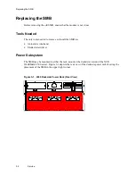
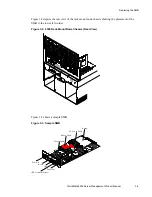
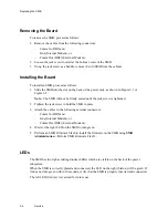
1. Slide the SMB into the slot on the back of the power rack, as shown in Figure 3-1 or
Figure 3-2.
Note: The SMB will not be firmly seated until the jack screw is tightened.
2. Tighten the jack screw to hold the SMB in place.
3. Attach the cables to the following external connectors:
–
Comm In (DB9) and
–
Line (Internal Modem), or
–
Comm Out (DB9) (External Modem).
4. Wait for the right LED on the SMB to turn green.
5. Perform an SMB Firmware Flash to install the firmware on the SMB using SMB
Administration <Perform SMB Firmware Flash>.
LEDs
The SMB has two light-emitting diodes (LEDs) which are visible on the back of the power
subsystem.
When the SMB is correctly placed and connected, the LED on the right (Status) will be green. If
it does not turn green within 30 seconds, verify that the SMB is properly inserted and connected.
The left LED (Service) is reserved for future use.
Summary of Contents for WorldMark 4300
Page 1: ...BD20 1398 B000 12 97 WorldMark 4300 Server Management Product Manual Release 2 0...
Page 6: ...Contents iv Table of Contents...
Page 10: ...Preface viii Preface...
Page 14: ...Monitored Controlled Attributes 1 4 Overview...
Page 50: ...Working With Event Actions 2 36 User Interface...
Page 66: ...Chassis Events A 10 SMB Event Code Tables...
Page 96: ...LANDesk UNIX Server Troubleshooting B 30 Troubleshooting...
Page 100: ...Index Index 4 WorldMark 4300 Server Management Product Manual...

