background image

4

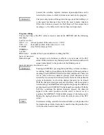
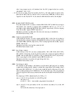
The 

 cursor-moving button.

It will move the cursor rightward, i.e. toward higher addresses; when the button is held
down, the cursor will be moving continuously. At the end of a line it will go automatically
to the first character of the next line. This function remains unchanged in STRING search
mode.

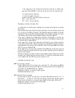
The 

 cursor-moving button.

It will move the cursor leftward, i.e. toward lower addresses; when the button is held down,
the cursor will be moving continuously. At the end of a line it will go automatically to the
first character of the next line. This function remains unchanged in STRING search mode.

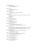
 - With the horizontal position left unchanged, the cursor will be moving downward across

the screen (toward higher addresses). It will perform a forward search in STRING search
mode.

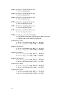
 - With the horizontal position left unchange, the cursor will be moving upward across the

screen (toward lower addresses). It will perform a backward search in STRING search mode.

 - Clear button.

It will clear the character in the position of the cursor. In the case of an error signal it can be
used as an overall clear button. When the editing is finished successfully, the message
PASSED will be blinking in the bottom line to signal that the program has passed the check
procedure. Under such conditions the clear button will cause the control to initiate the
automatic re-start of the system software ("PLC compilation").

 - INSERT mode.

The cursor is blinking in the area of a full character (otherwise being only an underlining)
to signal that the EDITOR is in insert mode. Under such conditions the new character will
be positioned in front of the one at which the cursor is blinking. Pressing the button again
will return the EDITOR from insert mode to transcript mode.

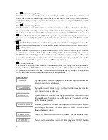
SOFT KEYS

Paging upward. A screen page will be turned upward across the

PAGE UP

screen toward lower addresses.

Paging downward. A screen page will be turned downward across the

PAGE DOWN

scree toward higher addresses.

Upward search of module. Moving upward across the screen toward

MODUL UP

lower addresses, the editor goes to the previous ":" character and thus
to the previous module.

Downward search of module. Moving downward across the screen

MODUL DOWN

toward higher addresses, the editor goes to the next ":" character and
thus to the next module.

Moving the cursor leftward to the first character of the previous word.

WORD LEFT

Statistics of the variables used in the PLC program. With the button

STATISTICS

Summary of Contents for 90

Page 1: ...NCT 90 MILLING MACHINE CONTROL INTEGRATED PCL ...

Page 2: ...Manufactured by NCT Automation kft H1148 Budapest Fogarasi út 5 7 Address 1631 Bp pf 26 F Phone 36 1 467 63 00 F Fax 36 1 363 6605 E mail nct nct hu ...

Page 3: ...ts of this Manual No reprinting even in extracts is permissible unless our written consent is obtained The text of this Manual has been compiled and checked with utmost care yet we assume no liability for possible errors or spurious data and for consequential losses or demages ...

Page 4: ...four TASKS alternating at intervals of 5 ms thus a given task will be on after every 20 ms The PLC Programmable Logic Control is one of the four tasks On its turn the PLC task is run invariably in the following manner 1 1 Structure of the PLC Task Activities in the PLC are 1 1 1 System s Activities Sampling 24V INPUTs Managing TIMERs Emergency state established in the event of a short circuited OU...

Page 5: ...ed by the task changer as soon as its turn is on again the execution can be resumed at the point of interruption The onlyexception is that the programmer gives up the remaining time with instruction J0 in favour of the rest of tasks Instruction J0 will cancel suspend the PLC task After 20 ms on completion of the activities mentioned in Sections 1 1 2 and 1 1 1 the execution of the program will be ...

Page 6: ...ton Select PLC sub mode Since any modification of the PLC program affects the PLC fundamental functions of the machine tool the mode will not become active unless a password is input to prevent an incidental entry in this mode or entry by an unauthorized person The buttons used in program editing have the following meanings Numeric entry buttons For a numeric entry the selected number appears in t...

Page 7: ...ished successfully the message PASSED will be blinking in the bottom line to signal that the program has passed the check procedure Under such conditions the clear button will cause the control to initiate the automatic re start of the system software PLC compilation INSERT mode The cursor is blinking in the area of a full character otherwise being only an underlining to signal that the EDITOR is ...

Page 8: ...ely in the position of the blinking cursor Input of character non numeric one Entering in EDIT PLC pressing the top Soft Keywill enter in charac CHARACT ter editing Under such conditions the Soft Keys will be assigned new meanings Each SOFTKEY field will exhibit maximum 8 characters let us refer to them as character groups Each character can be entered bytwo consecutive buttons pressed First selec...

Page 9: ...mpiler are described in detail in the Appendix In the case of a flawless PLC text the compiler returns a blinking message ASSEMBLED Now the programmer can carry on the work in one of two different ways Pressing button INS insert It is one of the data input buttons Now the EDITOR checks in again since however the compilation has been successful the PLC program appears on the screen in a typeset for...

Page 10: ...e modulefrombeingcompleted in its own time segment ARE STRICTLY FORBIDDEN 000 Cyclic PLC module Called at the beginning of life cycle in the next PLC time segment if command J0 is issued under the effect of instruction G000 Mandatory activities initialization of the system Prohibited instructions none Recommended program organization in module 000 000 C004 init module 100 PLC program NY405 no emer...

Page 11: ...ine checks to see that the desired speed can be output in the particular range If the desired speed is higher than the maximum speed of the current range it will effectuate the maximum speed if it is lower than the minimum speed in that range it will effectuate the minimum one in the range concerned The term desired speed refers to the programmed one modified by the spindle override In the case of...

Page 12: ...V analog signal can be output by setting the higher byte of OP to 0 055 command signal issue to the 2nd analog output 056 command signal issue to the 3rd analog output 057 command signal issue to the 4th analog output 058 command signal issue to the spindle analog output 3 4 PLC Subroutines to be Called from the Part Program 005 019 Those subroutines do not belong integrally to the PLC program the...

Page 13: ...must be set Mandatory activities turning the coolant on off Prohibited instructions none 007 Gear change module Called whenever the NC executes commands M11 M12 M13 M14 M15 M16 M17 or M18 At the time of entering in the module the contents of registers OP and RH004 will be 0BH 12H in accordance with commands M11 M18 respectively Prior to escaping from the module register RH054 must be set Mandatory...

Page 14: ...in module 008 Before returnig from module RH054 register should be updated If there is anyfailure FFFF should be written into register RH054 and make the NC to go into manual mode If the magazine is of turret type parameter 0102 M06 0 but the previous tool should be removed manually because it was loaded manually and then should be the new tool changed If the tool change is executed for M6 tool po...

Page 15: ...Called if the certain axis is moved byjog handwheel or returning to reference point The module is activated in all cases before and after a move command if output flag is Y460 1 When entering the module OP refers to the axes to be moved and the information whether the axes should be moved by feed or by rapid traverse Mandatory activities Unclamping brakes clutches of the assigned axes In case of e...

Page 16: ...n module 014 According to bit 15 of OP tool pot must be searched or the return tool number should be beeing blinked Waiting as long as the tool pot called in module 008 is in change position 015 016 017 A B C function module Calledifparameter1493A MISCEL 1 1496 B MISCEL 1 or1499C MISCEL 1 and the part program runs onto code A B or C Obligatory activities none Forbidden commands none 018 module for...

Page 17: ... 4 2 PLC NC Input Output Flags The input flags will inform the PLC about the states and modes of the NC The input flags are managed in the same manner as the 24V input lines The state of the line which may be 1 or 0 can be polled through opening conditional checks Innn NInnn or Vnnn The PLC communicates with the NC about its own states the executed or requested modes through output flags The outpu...

Page 18: ...1 0 when the PLC acknowledges this by the instruction U401 I417 state of part counter 1 the value of the part counter has reached the value specified on parameter PRTOTAL This flag is 1 at most for 100 msec after this event 0 the value of the part counter hasn t reached the value specified on parameter I440 Output of MON disable 1 MACHINE ON cannot be issued disastrous machine trouble 0 MACHINE ON...

Page 19: ... on the spindle spindle is oriented 0 position loop is not closed on the spindle I610 INPOS AXIS 1 1 axis 1 is in position FOL ERR 1 INPOS1 0 axis 1 is off position FOL ERR 1 INPOS1 I611 INPOS AXIS 2 1 axis 1 is in position FOL ERR 2 INPOS2 0 axis 1 is off position FOL ERR 2 INPOS2 I612 INPOS AXIS 3 1 axis 3 is in position FOL ERR 3 INPOS3 0 axis 3 is off position FOL ERR 3 INPOS3 I613 INPOS AXIS ...

Page 20: ... against transcript In the event of an attempt at transcript the NC returns the message WRITE IN MEMORY INHIBITED D403 protection of technological program memory against re writing cancelled Y404 MACHINE ON U404 activation of zero voltage output enabled The NC enables the internal NC READY state to be connected to the 24V output The 24V MACHINE ON output will be active only when lamp NC READY on t...

Page 21: ...xis 1 in positive direction and to blink error signal LIMq D416 limit position request cancelled Y417 LIM1 U417 limit stop position on axis 1 Signal to the NC to stop the movement of axis Z in positive direction and to blink error signal LIMq D417 limit position request cancelled Y424 LIM 5 U424 limit stop position on axis 5 Signal to the NC to stop the movement of axis 5 in negative direction and...

Page 22: ...point is being assumed D433 signals to the NC that axis 4 has run over the switch Y434 REF 5 U434 resetting the REF flag to default position While the machine s ref point is being assumed U434 signals to the NC that axis 5 has run off the switch D434 on state of REF flag While the machine s ref point is being assumed D434 signals to the NC that axis 5 has run over the switch Y435 REF 6 U435 resett...

Page 23: ...ction keys F1 F8 inhibited D456 function keys F1 F8 enabled Y457 JOG keypad inhibited U457 axis moving keypad inhibited D457 axis moving keypad enabled Y460 request for module 013 U460 013 module is called before and after an axis jog type movement D460 013 module is not called before and after an axis jog type movement Y461 request for module 013 in case of rapid traverse U461 013 module is calle...

Page 24: ...ol number programmed to address T or tool pot number RH002 programmed spindle command programmed to M3 M4 M5 or M19 RH003 programmed coolant codes M8 or M9 RH004 programmed range codes M11 M18 RH014 NUMERIC ENTRY 2 byte hexa RH015 START STOP 21H START 20H STOP 2 byte hexa RH016 SOFTKEY 0 7 soft keys 2FH pager 2 byte hexa RH017 JOG keys 2 byte hexa RH040 actual spindle speed measured from the spind...

Page 25: ...x0 1 resolution RH090 spindle speed with the override and the range limits taken into account 4 4 User s Registers and Flags This category includes 100 registers that can be addressed by words as well as by bits The registers will preserve their contents even when the control is turned off but they are not covered by the internal checksum controls Addressed by word F00 F99 Addressed by bits F000 F...

Page 26: ...the desired bit is tested This instruction is particularly useful for serving activities that require fast interventions The instruction is valid for physical input lines only it is has no meaning for input flags Its format is identical with that of instruction Innn Vnnn start of a conditional test by testing the change of an input line octal V000 V377 MACHINE PLC Start of a conditional test by te...

Page 27: ...ounting E finished counting Z The timer is decremented by the system program M0 M9 The timer can be loaded from the OP Smn and loaded into the OP Lmn brackets bywhich several conditions can be joined into a single condition For example Innn A Nynnn The logic value of the result of the conditional test is TRUE when input Innn is active and input Ynnn is cut out E FALSE ELSE branch of the conditiona...

Page 28: ...e U400 U777 PLC NC Under such conditions conditional test Ynnn gives a TRUE result conditional test NYnnn giving a FALSE result UOnnn direct setting up of the OUTPUT line in the instant the instruction is executed This instruction is particularly effective in serving activities that demand a fast intervention It is applicable to physical output lines only it has no meaning for output flags Its for...

Page 29: ...NPnnn NTnn NHn NMn NQnn L loading DATA in the OP For example LInn input byte of serial number nn is loaded in the lower byte of the OP and the input byte of serial number nn 1 will be loaded in the upper byte of the OP If command L stands to the right of a logic or arithmetic operand the result of the operation performed on the OP and the data will be loaded in the OP For example LInn OP LInn Feas...

Page 30: ... maximum character number of the message can be as much as 11 Under such conditions the message field has 11 characters Prior to displaying the content of the OP has to be converted to BCD PNE displaying the ASCII error message in the quotation marks in the 16 character long MESSAGE field of the screen Normal Error display PBE blinking the ASCII error message between the quotation marks in the 16 ...

Page 31: ...e instruction concerned ERROR 11 no ending bracket is found the opened conditional test group is not terminated ERROR 12 single quotation mark the opened spring print instruction is not terminated ERROR 13 N followed by illegal character Nxnnn ERROR 14 NL followed by illegal character NLxnn ERROR 15 NS followed by illegal character NSxnn ERROR 16 non decimal number or subscript in the instruction ...

Page 32: ...4 not interpreted character in the PLC program ERROR 45 PN PI PB not followed by M or E ERROR 46 PN PI PB followed by an illegal character ERROR 47 no terminating quotation mark or too long string contained in the PLC program ERROR 48 PxM or PxE followed by an illegal character ERROR 49 erratic PARAMETER subscript LRPnn where 0 nn 9 ERROR 50 P followed by an illegal character in instruction PRINT ...

Page 33: ...indle enable U001 enabled D001 disabled M5 O002 coolant U002 on M08 D001 off M09 O003 O004 O005 O006 O007 LUB lubrication U007 pump on D007 pump off Timers 100 ms timers H0 lubrication time as long as the counter is counting the pump is on H1 waiting the for turning the machine on After the MACHINE ON softkey was pressed the PLC is waiting for such a long time the emergency status to be off If dur...

Page 34: ... switch flag E D417 Z NI004 U416 sets X on limit switch flag E D416 Z NI001 U415 sets y on limit switch flag E D415 Z NI000 U414 sets y on limit switch flag E D414 Z NI007 U413 sets Z on limit switch flag E D413 Z NI005 U412 sets Z on limit switch flag E D412 Z Z end of condition not reference point return mode or not start state I006AI004 limit switches of X axis are considered as reference point...

Page 35: ...ted LRP002 0 if parameter CONST2 0 no lubrication E U007 lubrication pump on SH0 stores CONST2 into H0 timer lubrication time Z Z NH0AY007 lubrication time elapsed timer H0 and pump is on D007 pump off LRP001 loads CONST1 into OP register SM0 stores OP into M0 timer time between two lubrications Z Y405 tests emergency state flag G000 if emergency state initialization E G100 no emergency state goes...

Page 36: ... signal SY00 turns off all the outputs SY02 Y000 Y037 LRP001 loads CONST1 into OP SM0 stores OP into M0 timer time between two LRP003 loads CONST3 into OP spindle drive unipolar bipolar 0 unipolar DF090 E UF090 bipolar Z 014 label of internal cycle NI412 waiting for pressing machine on pushbutton NC PLC G014 Z U401 acknowlidgement of machine on pushbutton PLC NC U400 machine on pushbutton is lit P...

Page 37: ...12 waiting for the acknowledgement of the machine on button from the NC NC PLC G016 goes to the begining of the cycle Z D401 acknowledgement of the machine on button PLC NC R end of initialization subroutines written in PLC Spindle start stop module 005 5 module is called by M05 SRH052 M5 feedback to the NC 0 C052 0V output to the spindle command signal 1 W waiting for 100 msec 025 NI450 has spind...

Page 38: ... end of module 005 Coolant on off module 006 9 coolant code 9 M09 D002 coolant pump off E if not 9 then 8 NY001 not M05 spindle is on U002 coolant pump on Z Z SRH053 coolant code feedback to the NC R end of module 006 Module of spindle gear range change 007 LRH054 OP current gear range code SF12 stores new gear range code in F12 R Z if not equal to the current code 5 C005 calling 005 spindle stop ...

Page 39: ...ndle module with the code 5 LRH001 loads new tool code BCD converts it into BCD for display purpose PBM TOOL blinking message on display TOOL OP C150 waiting for START button LF14 loads the saved spindle code C005 restores spindle rotation LRH001 the new T code is fed back to the NC SRH051 SF10 saves the new T code into register F10 R end of module 008 Spindle speed module 009 LRH000 loads the pro...

Page 40: ...ction F090 bipolar or unipolar 0040 command signal at bipolar E FFC0 command signal at unipolar Z E 3 called by M3 U001 spindle on U000 M3 direction FFC0 command signal at unipolar Z Z U452 enable of spindle command signal C052 outputs OP as spindle command signal R return Module of axis jog 013 R return Module of tool change M06 014 R return tool change manually for T code Module function A 015 R...

Page 41: ... clear push button 150 SF20 saves OP 0 SRH015 resets clear button code register 151 label of the internal cycle waiting for clear button code LRH015 loads register 00A1 is it the code of clear button LF20 if yes restores OP R return Z G151 if not jumps back to 151 Waiting for the start button 152 SF20 saves OP 0080 SRH014 resets start button code registera ...

Page 42: ...39 153 label of the internal cycle waiting for start button code LRH014 loads register 008F is it the code of start button LF20 if yes restores OP R return Z G153 if not jumps back to 153 ...

Page 43: ...Y010 6 I011 28 I051 28 Y011 4 I012 10 I052 10 Y012 21 I013 9 I053 9 Y013 23 I014 31 I054 31 Y014 7 I015 30 I055 30 Y015 5 I016 12 I056 12 Y016 24 I017 11 I057 11 Y017 22 I020 25 Y020 10 I021 24 Y021 8 I022 6 Y022 25 I023 5 Y023 27 I024 27 Y024 26 I025 26 Y025 9 I026 8 Y026 28 I027 7 Y027 11 I030 21 Y030 20 I031 20 Y031 34 I032 2 Y032 32 I033 1 Y033 1 I034 23 Y034 2 I035 22 Y035 35 I036 4 Y036 3 I0...

Reviews: