background image

17 

Data Connectors  and Pin Outs 

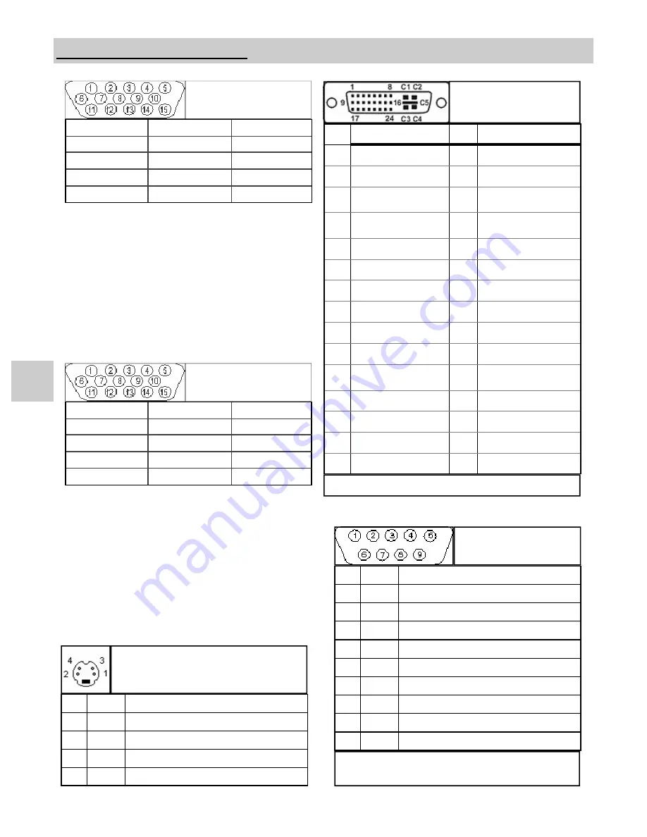
S-Video 

Pin  Name 

Description 

GND 

Ground (Y) 

GND 

Ground (C) 

Intensity (Luminance) 

Color (Chrominance) 

1 RED                 

6 GND   RED                 11 N. C.  

2 GREEN            

7 GND   GREEN                 

12 N. C.  

3 BLUE               

8 GND   BLUE                 

13 C. Sync / H. Sync.                      

4  N. C.  

9 N. C.  

14 V. Sync.  

5 GND TEST       

10 GND                  

15 N. C.                        

RGBS / YPbPr 

1 RED                 

6 GND   RED                 11 ID0  

2 GREEN            

7 GND   GREEN                 

12 ID1  

3 BLUE               

8 GND   BLUE                 

13 HORIZ SYNC                      

4  ID2  

9 N. C.  

14 VERT SYNC.  

5 GND        

10 SYNC GND                  

15 ID3                         

VGA 

PIN# 

SIGNAL 

PIN# 

SIGNAL 

  1  

T.M.D.S. DATA 2-  

16 

 HOT PLUG DETECT  

  2  

T.M.D.S. DATA 2+  

17 

 T.M.D.S. DATA 0-  

  3  

T.M.D.S. DATA 2/4 

SHIELD  

18  

T.M.D.S. DATA 0+  

  4  

T.M.D.S. DATA 4-  

19  

T.M.D.S. DATA 0/5 

SHIELD 

  5  

T.M.D.S. DATA 4+  

20  

T.M.D.S. DATA 5-  

  6  

DDC CLOCK  

21  

T.M.D.S. DATA 5+  

 7  

DDC DATA  

22  

T.M.D.S. CLOCK SHIELD  

  8  

N/C  

23  

T.M.D.S. CLOCK+  

  9  

T.M.D.S. DATA 1-  

24  

T.M.D.S. CLOCK-  

10  

T.M.D.S. DATA 1+  


11  

T.M.D.S. DATA 1/3 

SHIELD 

C1  

N/C 


12  

T.M.D.S. DATA 3- 

C2  

N/C  

13  

T.M.D.S. DATA 3+  

C3  

N/C  

14  

+5V POWER  

C4  

N/C  

15   

GND 

C5  

N/C  

DVI-D* 

Digital Input  

*

  Compliant with DVI 1.0 


Note: 

The following cables are available from NDS.


1.  Flash Upgrade Cable order part number: 35Z0009 

Serial and / or Touch 
Screen Control 

Pin  Name 

Description 

 NC  No Connection 

RXD  Touch Screen Data Receive 

TXD  Flash Upgrade & Touch Screen Transmit 

NC  No Connection 

GND  Ground 

NC  No Connection 

NC  No Connection 

NC  No Connection 

RXD  Flash Upgrade Receive Data 

Summary of Contents for Radiance Series

Page 1: ...Radiance 42 and 55 HR Medical Displays E N G L I S H...

Page 2: ......

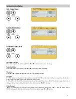
Page 3: ...Swap 6 GPIO 7 Display Set Up 8 SDI HD SDI Picture Menu 8 S Video Picture Menu 8 Composite Picture Menu 8 VGA SOG Picture Menu 9 RGBS YPbPr Picture Menu 9 DVI Digital Picture Menu 10 Color Menus 11 Se...

Page 4: ...ed in the presence of flammable anesthetics mixture with air oxygen or nitrous oxide It is the responsibility of the installer to test the display s earth ground to verify that it complies with the ho...

Page 5: ...rmined by consumer and is not warranted by NDS FCC and Council Directives of European Standards This device complies with Part 15 of FCC rules and 93 42 EEC of the Council Directives of European Stand...

Page 6: ...in a critical application and determine its usability For mission critical applications we strongly recommend that a replacement unit be immediately available Powering On The Unit Connect the power s...

Page 7: ...tch to Off when the RGBS and YPbPr signals will not be daisy chained to another display The REDRIVE switch is set to On when the RGBS and YPbPr signals will be daisy chained to a second display Electr...

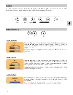
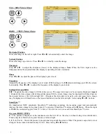
Page 8: ...splay the Brightness control menu Press the or button to adjust Primary brightness When a PIP image is visible press the Brightness Contrast button again to access the Secondary brightness control Set...

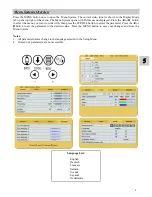
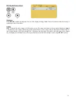
Page 9: ...stem opens with Picture menu displayed Press the or button to select the menu you want to work with then press the SCROLL button to select the parameter Press the or button to set the parameter to the...

Page 10: ...the right of the cursor Press the SCROLL button to highlight the desired input Finally press button to make it the primary input or press to make it the secondary input Selecting a secondary input is...

Page 11: ...erse order Pressing the SCROLL SWAP button will exchange the primary and secondary inputs and exchange their respective locations on the display Pressing the button a second time will restore the inpu...

Page 12: ...ress the SCROLL button to highlight the input that will be designated as Secondary 6 Select it by pressing the button an S appears in the column to the right of the cursor A small image of the signal...

Page 13: ...t losing video information Picture may have black bars top and bottom or left and right 1 2 3 4 5 or 6 Stretch the picture in proportional steps until the screen is filled The picture s aspect ratio i...

Page 14: ...til its largest dimension fills the screen Image may be displayed with black bars on the top and bottom or the left and right 1 1 Displays the video data in its native size and aspect ratio Image may...

Page 15: ...en The aspect ratio may not be accurately displayed Aspect Expands the video image until its largest dimension fills the screen Image may be displayed with black bars on the top and bottom or the left...

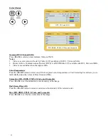
Page 16: ...mperature Press the or button to select one of the four preset color temperatures or User Selecting User allows you to individually adjust the values of Red Green and Blue Saturation SDI RGBS YPbPr S...

Page 17: ...light tubes in the display The display turns on when the input signal is restored Press the button to enable DPMS press the button to disable DPMS Auto Source Select on Searches through all possible i...

Page 18: ...es 2 Select the Defaults tab 3 Use the SCROLL button to select an available User Defaults EMPTY appears in available User Defaults 4 Press the to save the user s settings The EMPTY message will be rem...

Page 19: ...mage The displayed image may be too wide or too narrow and vertical banding and pixel jitter may appear in grays and light colors Adjust the Frequency until the image just fits the screen Horizontal p...

Page 20: ...15 7 Radiance Drawings and Dimensions Radiance 42...

Page 21: ...16 Radiance 55...

Page 22: ...A 0 4 T M D S DATA 4 19 T M D S DATA 0 5 SHIELD 5 T M D S DATA 4 20 T M D S DATA 5 6 DDC CLOCK 21 T M D S DATA 5 7 DDC DATA 22 T M D S CLOCK SHIELD 8 N C 23 T M D S CLOCK 9 T M D S DATA 1 24 T M D S C...

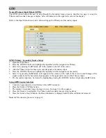
Page 23: ...Connector General Purpose Input and Output GPIO Swap Pressing the Swap button swaps the position and size of the Primary and Secondary images PIP Size The size of Secondary image increases each time...

Page 24: ...o nominal 700 1 550 1 Vertical Freq Hz max 85 85 Bandwidth MHz max 135 135 VGA Input signal level at 75 Ohm 0 7 V p p 0 7 V p p Pixel Clock MHz max 170 170 HD SDI SDI Input signal level 8 to 2 0 V p p...

Page 25: ...ted Graphics Inputs DVI DVI d VGA HD 15 Outputs HD SDI SDI BNC S Video DIN 4 RGBS YPbPr BNC x 5 RGBS YPbPr HD 15 Composite SOG BNC Proprietary Notice and Liability Disclaimer The information disclosed...

Page 26: ...Surgical Imaging LLC 5750 Hellyer Avenue San Jose CA 95138 USA Tel 408 776 0085 Fax 408 776 9878 EMail sevice ndssi com Europe Headquarters NDS Surgical Imaging BV Nijverheidscentrum 2D 2761 JP Zevenh...

Reviews: