NE41 17030-02 v1.0
D-POS II
- Technical Handbook
neat
21
8
Installation
It is recommended to install the antenna (either a loop or a ferrite antenna) as well
as preparing the necessary cabling for power, sync relays etc. prior to installing the
D-POS II unit.
Below is a recommended path when installing a D-POS II.
• Make the configurations and test the settings prior to installing (preferably on a table).
• Prepare the site where to install by installing the antenna, power supply, sync
cables etc..
• Mount the D-POS II.
• Connect the antennas, relays, external inputs, sync etc..
• Connect power to the unit.
• Run and test.
• Adjust RFID field if necessary.
8.1
D-POS II Connections
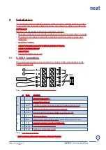
The picture below displays how and what to connect to the screw terminal in the
D-POS II control unit.
Sync
–
+
Picture 9.
Screw terminal in the control unit and connected parts
#
Text
Function
J2
1
+
Source power10-28V
DC
2
-
Source power Ground
3
ANT
*
A ferrite antenna should be connected between ANT and COM
4
COM
Common connection for ferrite/loop antenna
5
LOOP
*
A loop should be connected between LOOP and COM
J4
6
EXT
External activation
7
GND
Common ground for SYNC and EXT (internally connected to #2)
8
SYNC
Synchronization of two other D-POS units
9
RELAY
Galvanic isolated relay output
10
RELAY
Galvanic isolated relay output
Table 9.
Screw terminal connections
* Either a ferrite OR a Loop antenna can be connected!


