background image


78 


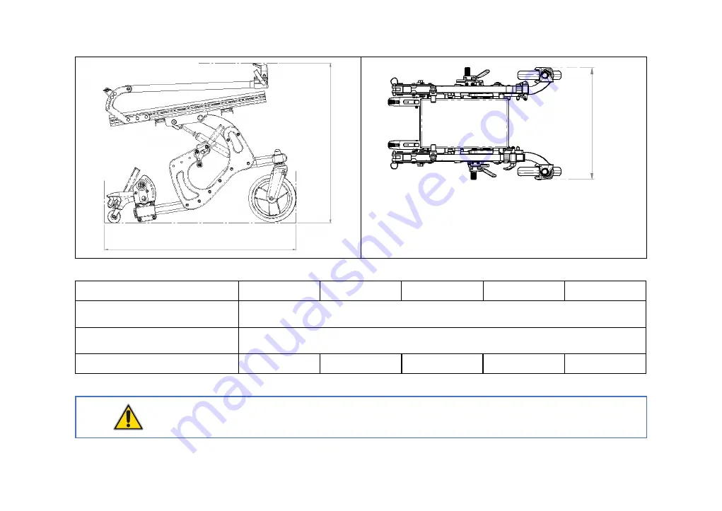
300 mm 

340 mm 

380 mm 

420 mm 

460 mm 

MIN 580 mm – MAX 590 mm 

MIN 620 mm – MAX 705 mm 

470 mm


510 mm


550 mm


590 mm


630 mm 


WARNING 

Folded width overcomes 350 mm. 


L


M


N


Summary of Contents for DYNA

Page 1: ...DYNA USER MANUAL 2021 07...

Page 2: ......

Page 3: ...ANUFACTURER Neatech it SRL via A de Curtis 4 A 80040 Cercola NA Italia Tel 39 081 555 1946 www neatech it info neatech it INTENDED USE The product is intended to be used for alleviation or compensatio...

Page 4: ..._______________ 17 2 6 Footplates height _________________________________________________________________________ 19 2 7 Footplates depth and angle____________________________________________________...

Page 5: ...__________ 53 3 6 4 Installation of the DAHL Docking stations in the vehicle _________________________________________________ 57 3 7 Transport and storage ____________________________________________...

Page 6: ...________________________________ 81 WARNING This symbol means presence of danger for the user or damage for the product Always follow instructions when this symbol is present PINCH HAZARD This symbol...

Page 7: ...horized modification to the product may increase the risk of personal injury and damage to the product itself All modifications should be done by an authorized service center Do not use any unauthoriz...

Page 8: ...gerous Please don t seat on armrests ANTI TIP DEVICES Using anti tippers substantially reduces your risk of falling over which can cause serious injury The Anti Tippers will keep you from falling over...

Page 9: ...he transfer distance Also be certain the wheel locks are engaged to prevent the wheels from moving Do not let children use the wheelchair without supervision The product is not intended to be dismantl...

Page 10: ...shift your weight or sitting position toward the direction you are reaching as the wheelchair may tip over Do not stand on the frame of the wheelchair Some pathologies may limit your ability to use yo...

Page 11: ...up or down slopes with a gradient than indicated in specifications of this manual Don t use the wheelchair up or down ramps that are not equipped with proper edge protection to prevent the wheelchair...

Page 12: ...facing with side slopes always use the wheelchair with great caution and make sure the seating system is in the default position Figure 3 Turning with the wheelchair When turning with the wheelchair a...

Page 13: ...he seating system is in the default position Always face an obstacle facing forward To help yourself to climb an obstacle an assistant can use the antitip bar to tip the wheelchair It is also possible...

Page 14: ...in case of accident In order to mount the pelvic belt please follow instructions below Version with dynamic seat Average needed time 5 min ALLEN WRENCH 5 mm Difficulty level Easy Figure 5 Place the p...

Page 15: ...6 Place the square nut inside the seat extruded tube Place the pelvic belt as shown in figure Repeat operation for both left and right side of the wheelchair Transfer into and out the wheelchair Users...

Page 16: ...f you really need to lift the wheelchair it is suggested to grab it with the help of at least one other people Grab the wheelchair using the seat tube as shown in figure Figure 7 WARNING It is necessa...

Page 17: ...ecycle the packaging materials follow instructions provided by your local waste disposal service The product is delivered already mounted and ready to use Before starting to use the product please che...

Page 18: ...e performed by an authorized service center Adjustment Type of operation Dimension see drawings in next pages Default position Seat angle B Assistant ND 0 Seat depth B Assistant A ND Armrests depth B...

Page 19: ...3 Backrest angle B Assistant D 90 Push handle height B Assistant ND ND Legrest angle B Assistant E 90 Table 1 A B c C C...

Page 20: ...4 E D...

Page 21: ...S A 46 cm POS B 48 cm POS C 50 cm POS D 52 cm POS E 54 cm Dynamic seat width 42 cm POS A 42 cm POS B 44 cm POS C 46 cm POS D 48 cm POS E 50 cm Dynamic seat width 42 cm POS A 50 cm POS B 52 cm POS C 54...

Page 22: ...40 cm Angle adjustable MIN 3 cm MAX 45 cm Angle adjustable Dynamic legrest MIN 8 cm MAX 47 cm D Fixed angle 90 90 Fixed angle 95 95 Fixed angle 100 100 Fixed angle 105 105 Fixed angle 110 110 Angle a...

Page 23: ...7 2 1 Seat angle Average needed time 1 min Difficulty level Easy In order to tilt the wheelchair use the levers as described in section 3 2...

Page 24: ...Version with dynamic seat Average needed time 20 min OPEN END WRENCH 10 mm Difficulty level Easy ALLEN WRENCH 4 mm Figure 8 Loosen the 6 screws shown in figure Repeat operation for both left and right...

Page 25: ...ut the metal sheets at the desired seat depth Screw again the 12 screws following instructions in reverse order Mount again the cushion Tighten again the 12 screws of the backrest paying special atten...

Page 26: ...10 POS B POS C...

Page 27: ...11 POS D POS E...

Page 28: ...evel Easy WARNING It is needed to set separately left and right seat depth Always set them at the same manner Figure 10 Loosen the 6 screws shown in figure Set the backrest according to the desired se...

Page 29: ...13 FIXED BACKREST With the fixed backrest there are only 4 screws per side Figure 11...

Page 30: ...depth Average needed time 5 min ALLEN WRENCH 4 mm Difficulty level Easy RIGHT AND LEFT SIDE It is possible to adjust separately left and right side Figure 12 Loosen the lever shown in figure and remo...

Page 31: ...15 Figure 13 Loosen the 2 screws shown in figure and set the depth of armrest clamp as desired Tighten again the 2 screws and put back the armrest Tighten the lever...

Page 32: ...5 min ALLEN WRENCH 4 mm Difficulty level Easy RIGHT AND LEFT SIDE It is possible to adjust separately left and right side Figure 14 Loosen the 2 screws shown in figure Set the armrest according to th...

Page 33: ...ty level Easy RIGHT AND LEFT SIDE It is possible to adjust separately left and right side SIDEPAD AND ARMREST HEIGHT It is better to adjust first armrest height then the sidepad RANGE Please be sure t...

Page 34: ...18 Figure 16 Unscrew the 2 screws shown in figure and set the position of sidepad as desired Screw again the 2 screws...

Page 35: ...AND LEFT SIDE It is possible to adjust separately left and right legrest if you have splitted footrest Figure 17 Unscrew the screw shown in figure with the 6 mm allen wrench while holding the nut behi...

Page 36: ...time 5 min ALLEN WRENCH 4 mm Difficulty level Easy RIGHT AND LEFT SIDE It is possible to adjust separately left and right legrest if you have splitted footrest INFORMATION This operation is not possi...

Page 37: ...shown in figure Set the position of the footplate according to desired depth Screw again the 2 screws 2 7 1 Angle adjustment Figure 19 Loosen the 2 screws shown in figure Set the position of the footp...

Page 38: ...2 2 8 2 Dynamic active backrest with spring Use the lever located on the push bar to move the backrest See section 3 2 Moreover it is possible to further adjust the backrest angle following instructi...

Page 39: ...sy Figure 20 Remove the backrest Unscrew the 4 screws shown in figure Set the position of the hardware highlighted in figure according to the desired backrest angle Screw again screws Repeat operation...

Page 40: ...m Difficulty level Easy Figure 21 Remove the backrest Unscrew the 4 screws shown in figure Set the position of the hardware highlighted in figure according to the desired backrest angle Screw again sc...

Page 41: ...t and right backrest angle Always set two parts of backrest at the same manner ADDITIONAL ADJUSTMENT After adjusted the angle of backrest as described above it is possible to adjust of more 20 simply...

Page 42: ...ge needed time 5 min Difficulty level Easy RIGHT AND LEFT SIDE It is possible to adjust separately left and right side Figure 23 Loosen the lever shown in figure and set the height of push handle as d...

Page 43: ...rest angle 2 10 1 Angle adjustable Angle adjustable dynamic legrest Average needed time 1 min Difficulty level Easy Figure 24 Loosen the lever shown in figure Set legrest angle as desired Tighten agai...

Page 44: ...legrest if you have splitted footrest DYNAMIC FUNCTION It is possible to use the legrest with springs as dynamic legrest simply losing the lever shown in figure In this way the legrest tube will move...

Page 45: ...29 DYNAMIC FUNCTION LOCK If needed in order to lock this movement you have to simply tighten again the lever shown in figure Figure 26...

Page 46: ...Easy Figure 27 To lock the wheelchair use the lever shown in figure WARNING When you operate the brakes operate always both left and right brake The use of the wheelchair with only one wheel locked c...

Page 47: ...ted on the upper part of push handle Press and hold it to operate the related function B This lever is located on the lower part of push handle Press and hold it to operate the related function C This...

Page 48: ...32 Functions A B C 1 Seat tilt 3 Dynamic backrest with pistons 3 1 1 Seat tilt 4 Dynamic active backrest with gas spring 1 4 1 Seat tilt 1...

Page 49: ...it free to move To do this act on levers located on push handles For more information see section 3 2 Dynamic seat can be used as a base for other seating systems Dynamic seat can be equipped with ad...

Page 50: ...ORMATION It is possible to unbind the movement of the backrest and of the seat In order to do that operation remove the two parts shown in figure Repeat operations for both side of the wheelchair Figu...

Page 51: ...ckrest or the movement of the backrest and of the seat if they are binded adding the locking mechanism shown in figure Figure 29 INFORMATION In order to facilitate user positioning it is possible to l...

Page 52: ...ose if to leave free the dynamic movement of legrest or to block it in a certain position simply acting on a lever Average needed time 1 min Difficulty level Easy RIGHT AND LEFT SIDE It is possible to...

Page 53: ...37 Figure 30 Loosen the lever shown in figure to let the legrest free to move Tighten the lever shown in figure to block the legrest in a certain position...

Page 54: ...allows you to accommodate foot movements It is possible to choose if leave free the dynamic movement of footrest or block it in a certain position A POSSIBLE VALUES 90 101 113 124 135 Average needed t...

Page 55: ...39 Figure 31 Loosen the screw shown in figure to let the legrest free to move Tighten the screw shown in figure to block the legrest in a certain position...

Page 56: ...free to move the range of movement is 45 It is possible to limit this range screwing the screw shown in figure Average needed time 5 min ALLEN WRENCH 4 mm Difficulty level Easy RANGE 45 90 135 RANGE 2...

Page 57: ...justable called Dahl VarioDock The lock plate and wheelchair adaptation kits are identical for both docking stations and both are suitable for securing the wheelchair Please also refer to Dahl Enginee...

Page 58: ...ius will generally provide greater ease of vehicle access and maneuverability to a forward facing position The wheelchair is designed to be secured facing forward when used as a seat in a motor vehicl...

Page 59: ...ir in a car with a different positioning WARNING In any case when using the wheelchair as a seat in a motor vehicle the seat height must be at the lowest position WARNING The wheelchair has lots of co...

Page 60: ...he movement of the gas springs with the locking system shown in the picture Always repeat the operation for the left and right side of the wheelchair WARNING Safety of wheelchair and user can t be ass...

Page 61: ...r WARNING Safety of wheelchair and user can t be assured when the movement of legrest is not correctly locked while using the wheelchair as a seat in a motor vehicle Figure 35 WARNING When possible ot...

Page 62: ...s at the front and 4 straps at the back Never use equipment not labeled with ISO 10542 WARNING Use WTORS Wheelchair Tie down Occupant Restraint System in accordance with the WTORS manufacturer instruc...

Page 63: ...47 Tie down strap angles Figure 36 Preferred angles for front tie down straps Figure 37 Preferred angles for rear tie down straps...

Page 64: ...48 Use the tie down points marked with the symbol shown in figure Hook the wheelchair in 4 points two in the front part and two in the rear part Figure 38...

Page 65: ...of the wheelchair have just a postural function Never use them to protect the user when using the wheelchair as a seat in a motor vehicle Occupant restraints should make full contact with the shoulde...

Page 66: ...AWAY FROM THE BODY BY WHEELCHAIR COMPONENTS SUCH AS ARMRESTS OR WHEELS PROPER BELT RESTRAINT FIT BELT RESTRAINTS SHOULD MAKE FULL CONTACT WITH THE SHOULDER CHEST AND PELVIS AND PELVIC BELTS SHOULD BE...

Page 67: ...restraint belt must be worn low across the front of the pelvis so that the angle of the pelvic belt is within the optional or preferred zone of 30 to 75 to the horizontal A steeper greater angle with...

Page 68: ...ant restraint system shall be located 10 60 mm outside wheels on each side The pelvic belt must be worn low across the front of the pelvis so that the angle of the pelvic belt is within the optional o...

Page 69: ...Dahl Docking system Mk II 1 Dahl Docking station Dahl Docking station 2 Lock plate and spacer 3 Lock pin 4 Red LED 5 Green LED 6 Control panel 7 Release button 8 Manual emergency release lever 9 Manua...

Page 70: ...til the lock plate is either fully engaged or else the wheelchair is removed from the docking station As an indication that the wheelchair is properly secured the warning tone will cease the red lamp...

Page 71: ...the locking pin is automatically locked activated again Move the wheelchair away from the docking station within this 5 second period Do not attempt to reverse out of the docking station until the red...

Page 72: ...ry The red release arm is also pushed to one side and should be held there whilst the wheelchair moves away If the described manual release procedures fail an emergency release tool made from red plas...

Page 73: ...of vehicles which must be respected by the fitter Please contact Dahl Engineering for further information about approved vehicles and fitting positions CONTACT INFORMATION For more information contac...

Page 74: ...AHL Kit 501905 2 1 500673 Spacer 8 mm DAHL Docking station 3 1 501935 Lock plate with bolts DAHL Docking station 4 5 502786 Lock nut M8 DIN 985 DAHL Kit 501905 5 6 Bolt M6x60 DIN 912 8 8 NEATECH Wheel...

Page 75: ...M6x50 screws shown in figure Replace those screws with 3 screws M6 x 60 in order to fix the main part of the adaptive kit to the side panel of the wheelchair Repeat this operation for both left and ri...

Page 76: ...60 Figure 44 Fix 3 screws shown in figure on the lock plate together with the spacer using nuts not showed in figure to lock them...

Page 77: ...ck plate together with the spacer using nuts not showed in figure to lock them WARNING Do not use any other screws than those supplied from DAHL quality 14 9 torx key size 27 because standard screws w...

Page 78: ...so the user should provide himself for it The used package must be water and dust resistant and strong enough to protect the product from any hurts When inserting the product into the package protect...

Page 79: ...gure Remove the legrest Repeat operations for both left and right side of the wheelchair Remove traction wheels Figure 48 Press the button shown in figure and pull away the axis and the wheel Repeat o...

Page 80: ...64 Remove armrest Figure 49 Loosen the lever shown in figure Remove the armrest Repeat operations for both right and left side of the wheelchair...

Page 81: ...iculty level Easy ALLEN WRENCH 5 mm Figure 50 Remove the backrest Unscrew the screw shown in figure with the 5 mm allen wrench while holding the nut behind with the 10 mm open end wrench Low the backr...

Page 82: ...66 NON FIXED BACKREST To low down the backrest it is sufficient to remove the axis shown in figure Repeat operation for both left and right side of the wheelchair Figure 51...

Page 83: ...uct must be performed by an authorized service center 4 1 Cleaning WARNING To clean the product do not use high pressure water spray devices Do not use stain removers solvents acids PLASTIC AND METAL...

Page 84: ...B Assistant Check all gas springs to verify any oil leakage Monthly B Assistant Check all adjustment screws 6 months B Assistant WHY IT IS IMPORTANT TO REGULARLY CHECK THE PNEUMATICH WHEELS PRESSURE...

Page 85: ...2 1 Brake adjustment Average needed time 5 min ALLEN WRENCH 5 mm Difficulty level Easy Figure 52 Loosen the 2 screws shown in figure Set the armrest according to the desired height Tight again the 2 s...

Page 86: ...at the brake correctly locks the wheel WARNING If you have pneumatic wheels before adjusting the brake always check for their pressure and usury WARNING It is needed to set separately left and right b...

Page 87: ...cture WARNING This section refers only to wheelchair with pneumatic wheels 4 3 1 User information Traction wheels Figure 53 Rise the wheelchair Press the button shown in figure and pull away the pin R...

Page 88: ...se the wheelchair Unscrew the screw shown in figure while holding the nut behind Remove the wheel Contact an authorized service center for the repair or the substitution of the damaged wheel When the...

Page 89: ...o repair or substitute the wheel 4 4 Reuse The product is suitable for reuse Before dispensing it the product must be cleaned and subjected to maintenance The operating instructions are included in th...

Page 90: ...46 cm 100 kg Overall dimensions width length and height ready for use and when folded or dismantled mm min max Height MIN 1060 MAX 1200 Width MIN 470 mm MAX 630 mm Length with legrest MIN 910 mm MAX...

Page 91: ...MAX 90 Armrest to seat distance min max mm MIN 200 mm MAX 340 mm The wheelchair conforms to requirement and test methods for static impact and fatigue strengths ISO 7176 8 yes no Yes The wheelchair c...

Page 92: ...76 5 1 Drawings A C B E H J G K...

Page 93: ...460 mm B 470 mm 510 mm 550 mm 590 mm 630 mm C 410 mm 450 mm 490 mm 530 mm 570 mm E MIN 180 mm MAX 270 mm MIN 270 mm MAX 360 mm G MIN 30 mm MAX 470 mm H 470 mm J 300 mm MIN 610 MAX 720 400 mm MIN 665...

Page 94: ...78 A 300 mm 340 mm 380 mm 420 mm 460 mm L MIN 580 mm MAX 590 mm M MIN 620 mm MAX 705 mm N 470 mm 510 mm 550 mm 590 mm 630 mm WARNING Folded width overcomes 350 mm L M N...

Page 95: ...the following document the Customer is the holder of the financial document issued by the manufacturer following the supply of the product PRODUCT Product is the good supplied by the manufacturer to t...

Page 96: ...r Wheels Padded parts polyurethane foams viscoelastic Upholstery including canvas Handles and knobs Fuses and bulbs Electric motor brushes Filters The warranty is limited to damage related to the prod...

Page 97: ...81 6 2 Serial number For any report or assistance request please communicate the serial number mentioned on the label in the position shown in figure Figure 55...

Page 98: ...Note...

Page 99: ......

Page 100: ......

Reviews: