background image


www.neatech.it 

34 

7.  FAULT, REPAIR AND ASSISTANCE 


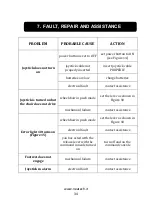
PROBLEM 

PROBABLE CAUSE 

ACTION 

Joystick does not turn 

on 

power button is set to OFF  set power button to ON 

(see Figure 14) 

joystick cable not 

properly inserted 

insert joystick cable 

PROPERLY 

batteries are low 

charge batteries 

electrical fault 

contact assistance 

Joystick is turned on but 

the chair does not drive 

wheelchair in push mode 

set the lever as shown in 

Figure 18 

mechanical failure 

contact assistance 

Error light 10 turns on 

(Figure 15) 

wheelchair in push mode 

set the lever as shown in 

Figure 18 

electrical fault 

contact assistance 

you has acted with the 

release lever with the 

command console turned 

on 

turn off and on the 

command console 

Footrest does not 

engage 

mechanical failure 

contact assistance 

Joystick in alarm 

electrical fault 

contact assistance 


Summary of Contents for Speedstar

Page 1: ...USER MANUAL with CE Mark Statement Supplier This manual must be given to the user of the wheelchair User Before using this wheelchair read this entire manual and save for future reference...

Page 2: ...ola NA Italy Tel 39 0815551946 Fax 39 0815552507 From the date of the delivery of the wheelchair the warranty period is two years for the chassis and six months for the batteries The warranty will exp...

Page 3: ...e conditions laid down by European Directive 93 42 according to the criteria for classification of annex IX of this Directive the Speedstar is classified as class I medical device It also complies wit...

Page 4: ......

Page 5: ...Table of contents WARNINGS 1 1 WHEELCHAIR PRESENTATION 4 2 STARTING UP 5 3 USE OF THE WHEELCHAIR 13 4 ADJUSTMENTS 20 5 ACCESSORIES 26 6 CONTROL AND MAINTENANCE 31 7 FAULT REPAIR AND ASSISTANCE 36...

Page 6: ...top computers two way radios and commercial radio and television broadcast antennas PLEASE USE CAUTION in the presence of these devices EMI can cause your chair without warning to Release its brakes M...

Page 7: ...The wheelchair is not intended to be used as a seat on motor vehicles PINCH HAZARDS WARNING Make sure your feet do not hang up or get caught in the space between the footrests In general make sure yo...

Page 8: ...ntially reduces your risk of falling over backwards which can cause serious injury If you are afraid of tipping over use the Anti Tippers The Anti Tippers will keep you from falling over but they will...

Page 9: ...Frame and canvas are available in different colors Characteristic Pair of 300W engines Mechanical electromagnetic parking brake Custom colors Electronic tilting Maximum speed 9 km h Joystick 320 mm w...

Page 10: ...elivery or immediately thereafter to ensure that no damage has resulted from a careless transport Make sure the surface of the device is not damaged scratched bent etc Any fault or damage found must b...

Page 11: ...package of the Speedstar on a stable and secure surface and remove straps with scissors Pull away the box as shown in Figure 2 Figure 2 Inside the box there is Speedstar wheelchair N 1 pair of footre...

Page 12: ...igure 4 Figure 5 Unlock the engine with the lever as shown in Figure 4 and Figure 5 and slide gently down the Speedstar from the pallet After positioning the Speedstar in a safe place return the lever...

Page 13: ...2 STARTING UP www neatech it 8 Place the backrest Raise the backrest from position A to position B by gently pulling the backrest in an upright position A Figure 6 B Figure 7...

Page 14: ...2 STARTING UP www neatech it 9 Make sure that the pins are inserted correctly as shown in Figure 8 and Figure 9 Figure 8 Figure 9...

Page 15: ...put the armrest into the holder and tighten the lever M Figure 10 Connection of the Joystick Connect the cable of the joystick as shown in Figure 11 Make sure it is completely connected If it appears...

Page 16: ...2 STARTING UP www neatech it 11 Place the footrests Figure 12 Correctly insert the footrests into the holder as shown in Figure 12 Tighten securely the lever C Figure 13...

Page 17: ...long time make sure that you set the switch I OFF as shown in in Figure 14 You should keep the Speedstar in a place free from dust and moisture and away from heat sources If you must ship the Speedsta...

Page 18: ...checks Checking tire pressure Verify that the tire pressure is consistent with the values given in the table Front wheels 3 0 bar Rear wheels 1 5 bar Checking battery charge level Check the battery c...

Page 19: ...ndicator 8 Hazard warning 9 Indicator towards Left 10 Error indicator 11 On off button 12 Fully charged battery indicator 13 Right turn indicator 14 Seat movements selector 2 15 Speedometer 16 MAX spe...

Page 20: ...e the switch to turn on the chair If the problem still continues please contact technical support Figure 17 Figure 18 Seeing Figure 15 and Figure 16 use the button 11 to turn on the command console Us...

Page 21: ...signals Lights 3 and 4 flash to indicate the successful entry into service of the indicators Use button 17 to turn on or off the headlights Light 19 turns on or turns off to indicate the successful t...

Page 22: ...ode use switch I see Figure 14 to turn off the Speedstar and set the release engine lever as shown in Figure 19 and in Figure 20 Figure 19 Figure 20 WARNING In the push mode the electromechanical brak...

Page 23: ...harger to recharge the batteries The manufacturer is not responsible for damage to person or property resulting from the use of other chargers Charging in progress Battery error Charging 80 Wrong pola...

Page 24: ...erature However the approximate charging time is about 7 9 hours If the charge duration was reduced about 1 hour that is a sign of failure Contact the vendor for a possible replacement of batteries Do...

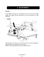
Page 25: ...justments on the armrests height width and depth Shown operations can be performed on both armrests Height Figure 21 Seeing Figure 21 loosen the screws A and set armrests height to desired value and r...

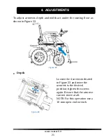
Page 26: ...the seating floor as shown in Figure 22 Figure 22 Depth C Figure 23 Loosen the 4 screws indicated in Figure 23 and move the armrest to the desired position tighten the screws again Be sure that the ar...

Page 27: ...ith the directions indicated to reach the desired position and tighten the screws again NOTE For this operation use a 6 mm allen wrench Joystick Loosen the lever L as shown in Figure 25 so it is possi...

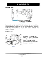
Page 28: ...ation Rotate footrests to reach the desired position Tighten the screws again Figure 26 Footrests depth Unscrew the screws shown in Figure 26 put the footrest in one of three positions shown in Figure...

Page 29: ...he desired height aligning the footrest to one of the available holes NOTE For this operation use a 6 mm allen wrench and a 13 mm open end wrench Backrest depth Figure 29 Seeing Figure 29 loosen the s...

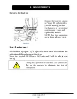
Page 30: ...eturn and tighten the screws NOTE For this operation use a 4 mm allen wrench Seat tilt adjustment Push button 4 Figure 15 A light near the button will confirm the activation of this adjustment functio...

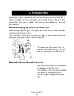
Page 31: ...u can adjust the inclination of the footrests with the aid of the joystick The controller allows you to select the type of movement only left footrest only right footrest both footrests Figure 31 To e...

Page 32: ...and recline the backrest to the desired inclination and release the lever X Powered reclining backrest With the aid of two electronic pistons the user can recline the backrest with the joystick Figure...

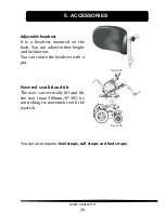
Page 33: ...an adjust either height and inclination You can rotate the headrest with a pin Figure 35 Powered seat lift and tilt The user can vertically lift and tilt the seat max 300mm 0 30 by controlling its mov...

Page 34: ...on Application field This article is made for purpose of fixing persons in the wheel chair on stretchers beds or something else This item should not be applicated in motor vehicles Cleaning For cleani...

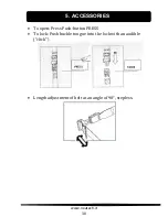
Page 35: ...5 ACCESSORIES www neatech it 30 To open Press Push button PRESS To lock Push buckle tongue into the lock with an audible click Length adjustment of belt at an angle of 90 stepless...

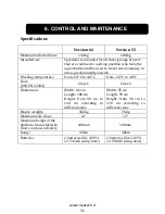
Page 36: ...de Working temperature from 10 C to 40 C from 10 C to 40 C Class UNI EN 12184 Class C Class C Dimensions Width 66 cm Length 108 cm Height from 90 cm to 110 cm according to different sizes Width 55 cm...

Page 37: ...6 CONTROL AND MAINTENANCE www neatech it 32...

Page 38: ...rom water and humidity For plastic or metal parts use a soft cloth moistened with a non aggressive detergent For pads linings and covers of the seat and backrest use warm water and mild detergent Do n...

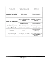
Page 39: ...e Joystick is turned on but the chair does not drive wheelchair in push mode set the lever as shown in Figure 18 mechanical failure contact assistance Error light 10 turns on Figure 15 wheelchair in p...

Page 40: ...ert the release lever correctly mechanical failure contact assistance Wheelchair does not have a good grip Tires are not set to the correct value of pressure Set the tires pressure to the correct valu...

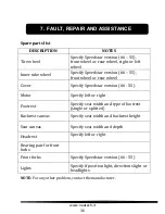
Page 41: ...over Specify Speedstar version 66 55 Motor Specify left or right Footrest Specify seat width and type of footrest single or splitted Backrest canvas Specify seat width and backrest height Seat canvas...

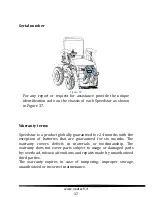
Page 42: ...ar is a product globally guaranteed for 24 months with the exception of batteries that are guaranteed for six months The warranty covers defects in materials or workmanship The warranty does not cover...

Page 43: ...7 FAULT REPAIR AND ASSISTANCE...

Page 44: ...SER MANUAL SPEEDSTAR NEATECH IT Our Mission is to transfer technology and solutions from the aerospace industry to the disability sector We are proud to offer the highest quality products and solution...

Reviews: