background image

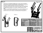
DETAIL  C

DETAIL  D

PARTS USED IN STEP 6

QTY

DESCRIPTION

PART NUMBER

4

5/16"-18 x 3/4" Flange Bolt

5/16-18x3/4FB

4

5/16"-18 Whiz Lock Nut

5/16-18SFN

4

1.5" Handrail P-Clamp

HRC1500

6

Self-Tapping Screw

Floor Screw

4

1.5" Handrail, Swaged

TR1506006

2

1" Handrail, Swaged

TR1006006

C

D

DRAWN

Marcus Wilmsmeyer

CHECKED

QA

MFG

APPROVED

1/17/2019

Greene Galvanized Stairs

East Lynn, IL 217.375.4244

www.greenebinstairs.com

TITLE

A-Series Roof Stairs - 3-Step 
Assembly Instructions

SIZE

A

SCALE

DWG NO

IN-ART5003

REV


SHEET

 9  

OF

 9 

1/22

Figure 9

Step 6

A.

Taking the four (4) TR1506006 Swaged Pipes (1.5" dia.), position the pipes as 
shown in Figure 9, Detail C. Secure the pipes to the posts using four (4) HRC1500
P-Clamps, four (4) 5/16" Flange Bolts, and four (4) 5/16" Lock Nuts.

B.

After the four TR1506006 have been position to the desired location, use four (4) 
Self-Tapping Screws and secure the 1.5" pipe to the P-Clamp. The screws should 
be drilled through the bottom of the P-clamp, to minimize interference with 
hands.

C.

Take the two (2) TR1006006 Swaged Pipes (1" dia.), and position them as shown
in Figure 9, Detail D. Secure them to the posts by using two (2) Self-Tapping 
Screws. There is a hole on the post to aid in starting the Self-Tapping Screw.

Summary of Contents for ART5003

Page 1: ...ART5003 Assembly Instructions Greene Galvanized Stairs...

Page 2: ...Stair Post w Guardrail ART 1016 1 Roof Stair Post Brace Right ART 1004 1 Roof Stair Post Brace Left ART 1007 2 Roof Stair Leveling Plate ART 1011 4 3 Step Side Rail ART 5003 3 30 x 11 Stair Step Tread...

Page 3: ...List ES 5015 48 0 ART 1007 ART 1004 23 0 ART 1015 ART 1016 45 25 ART 1011 10 0 ART 5003 AS00030 30 0 ART 1001 47 5 TR1504606 TR1004606 HRC1500 Floor Screw 5 16 18x3 4FB 5 16 18SFN 1 1 1 1 1 1 46 5 46...

Page 4: ...nstructions SIZE A SCALE DWG NO IN ART5003 REV SHEET 4 OF 9 1 14 Step 1 Figure 1 Figure 2 A Place the ART 1007 and ART 1004 braces against the ES 5015 Roof Mount as shown in Figure 1 The braces flange...

Page 5: ...s East Lynn IL 217 375 4244 www greenebinstairs com TITLE A Series Roof Stairs 3 Step Assembly Instructions SIZE A SCALE DWG NO IN ART5003 REV SHEET 5 OF 9 1 9 ART 1011 Step 2 A Take two 2 ART 1011 Le...

Page 6: ...217 375 4244 www greenebinstairs com TITLE A Series Roof Stairs 3 Step Assembly Instructions SIZE A SCALE DWG NO IN ART5003 REV SHEET 6 OF 9 1 9 Step 3 A Place three 3 AS00030 Step Treads in line with...

Page 7: ...East Lynn IL 217 375 4244 www greenebinstairs com TITLE A Series Roof Stairs 3 Step Assembly Instructions SIZE A SCALE DWG NO IN ART5003 REV SHEET 7 OF 9 1 10 Step 4 A Take the two 2 Cross Braces and...

Page 8: ...Lynn IL 217 375 4244 www greenebinstairs com TITLE A Series Roof Stairs 3 Step Assembly Instructions SIZE A SCALE DWG NO IN ART5003 REV SHEET 8 OF 9 1 7 Step 5 A Using six 6 5 16 Flange Bolts and six...

Page 9: ...9 OF 9 1 22 Figure 9 Step 6 A Taking the four 4 TR1506006 Swaged Pipes 1 5 dia position the pipes as shown in Figure 9 Detail C Secure the pipes to the posts using four 4 HRC1500 P Clamps four 4 5 16...

Reviews: