Making Connections 3-4
5.
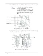
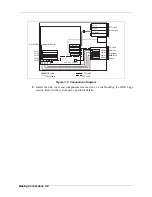
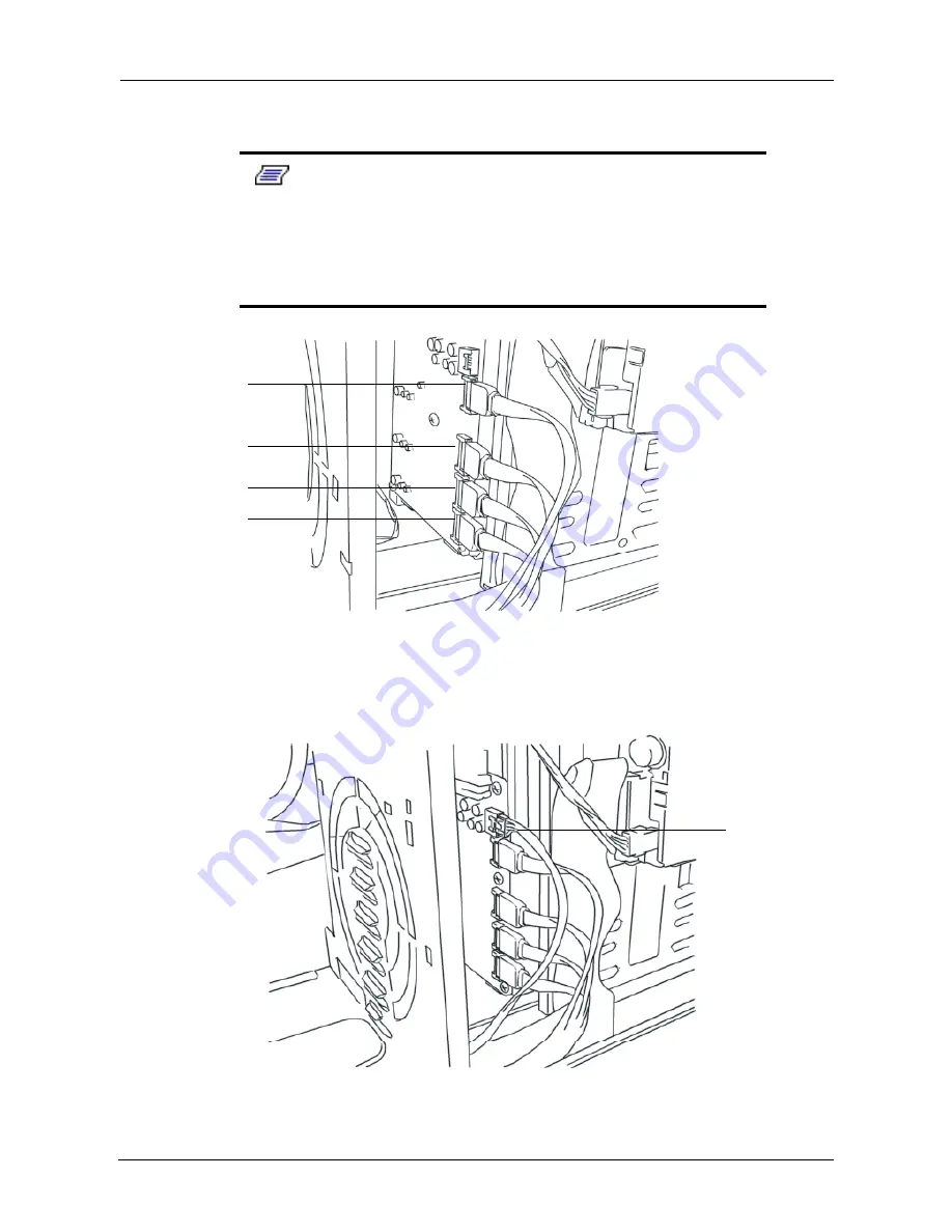
Connect the four cables to the HDD cage. When connecting cables, the channel
numbers on the HDD cage must match the numbers on the cables.
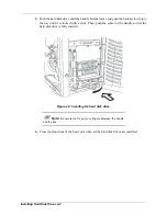
Figure 3-4: Connecting the S-ATA Cables
6.
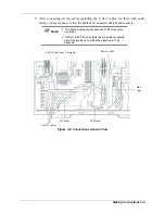
Connect the I2C cable to the I2C connector on the HDD Cage. Connect the connector
at the other end of the cable to the Disk Array Controller. Refer to the Disk Array
Controller user’s guide for more details.
Figure 3-5: Connecting the I2C Cable
Note:
- You can see the channel numbers (CH1, CH2, CH3, and
CH4) near the cable connectors.
- Connect the cables to the connectors aligned in the order of
CHANNEL1 (Port1), CHANNEL2 (Port2), CHANNEL3
(Port3), and CHANNEL4 (Port4) from the bottom to the top.
- Insert the cables straight into the connectors of the HDD
Cage.
CHANNEL4 (Port4)
CHANNEL3 (Port3)
CHANNEL2 (Port2)
CHANNEL1 (Port1)
I2C cable
Summary of Contents for 120Ef
Page 1: ... User s Guide HDD Cage ...
Page 2: ......
Page 4: ......
Page 6: ...iv ...
Page 17: ...System Overview 1 1 1 System Overview Identifying items Part Names and Functions ...
Page 20: ...System Overview 1 4 ...
Page 21: ...Handling the HDD Cage 2 1 2 Handling the HDD Cage ...
Page 24: ...Handling the HDD Cage 2 4 ...
Page 25: ...Making Connections 3 1 3 Making Connections ...
Page 31: ...Installing Hard Disk Drives 4 1 4 Installing Hard Disk Drives ...
Page 35: ...Appendix A 1 Appendix Operation Maintenance Specifications ...
Page 37: ... ...

