78K0/Fx2 – CAN it!
3.1 RESET button SW1
SW1 is a reset button. It activates the power on reset. It is connected to the reset input of the 78K0/FF2
CPU module.
3.2 User button SW2
SW2 is a push button connecting V
CC
to external interrupt input INTP0 of the microcontroller. This is equal
to port P120 of the 78K0/FF2 device. The port may be programmed to generate interrupt INTP0. The
necessary initialisation for this purpose is described in the user’s manual of the 78K0/FF2 device. The
port is connected to a 4.7K pull down resistor.
3.3 User button SW3
SW3 is a push button connecting V
CC
to external interrupt input INTP1 of the microcontroller. This is equal
to port P30 of the 78K0/FF2 device. The port may be programmed to generate interrupt INTP1. The
necessary initialisation for this purpose is described in the user’s manual of the 78K0/FF2 device. The
port is connected to a 4.7K pull down resistor.
3.4 Configuration switch SW4
The different operation modes of the
78K0/Fx2 – CAN it!
board can be set by SW4 switches S1-S4.
SW4
Factory settings
Operation Mode
S1 OFF
Normal
operation
mode
S2 OFF
OCD
disabled
S3 OFF
UART60
select
S4
OFF
LIN bus disabled
Table 1: Configuration switch SW4, factory settings
3.4.1 Operation mode selection SW4/S1
SW4 switch S1 controls the operation mode of the
78K0/Fx2 – CAN it!
board. Setting SW4/S1 to ON
allows to reprogram the internal FLASH memory of the 78K0/FF2 device using the FPL3 FLASH
programming software.
SW4, S1
Operation mode
OFF (default)
Normal operation mode
ON
FLASH memory programming mode
Table 2: Operation mode selection SW4/S1
Within normal operation mode the user program stored in the FLASH memory of 78K0/FF2 device is
executed.
3.4.2 On-Chip debug mode selection SW4/S2
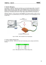
SW4 switch S2 controls the On-Chip debug function of the 78K0/FF2 device. Setting switch S2 to ON
allows to use the On-Board debug function of the
78K0/Fx2 – CAN it!
board or alternative connecting the
QB-78K0MINI On-Chip debug emulator to the 78K0/FF2 CPU module, connector CN7.
SW4, S2
Operation Mode
OFF (default)
OCD disabled
ON OCD
enabled
Table 3: OCD mode selection SW4/S2
For more details on how to configure
78K0/Fx2 – CAN it!
in order to use On-Chip debugging please refer
to
CHAPTER 5, ON-CHIP DEBUGGING
.
14


