background image

78K0/Fx2 – CAN it!


9.4.4 [Help] menu 

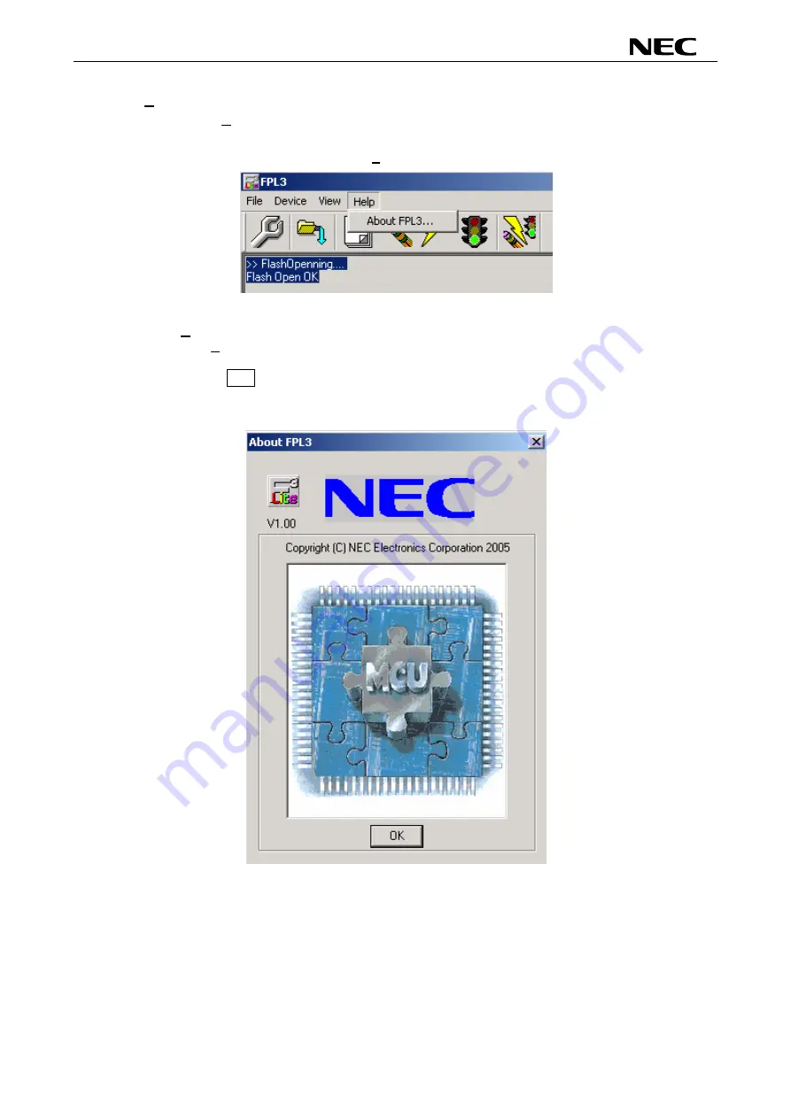
Clicking the [Help] menu displays the following pull-down menu: 


Figure 53: [Help] Menu 


(1) [About FPL3] command 

 The 

[About FPL3] command opens the program entry window as shown below and 

indicates the version. 


Clicking  OK  terminates the display. 


Figure 54: About FPL3 Window 


58


Summary of Contents for 78K0/Fx2

Page 1: ...User s Manual 78K0 Fx2 CAN it Demonstration Kit for the F_Line Family Document No 78K0FX2CANITV101 Date Published June 2006 NEC Electronics Europe GmbH ...

Page 2: ...ty of NEC Electronics products customers agree and acknowledge that the possibility of defects thereof cannot be eliminated entirely To minimize risks of damage to property or injury including death to persons arising from defects in NEC Electronics products customers must incorporate sufficient safety measures in their design such as redundancy fire containment and anti failure features Descripti...

Page 3: ...his equipment has no autonomous function Consequently this equipment is not marked by the CE symbol EEDT ST 0005 10 Redemption of Waste Electrical and Electronic Equipment WEEE in accordance with legal regulations applicable in the European Union only This equipment including all accessories is not intended for household use After use the equipment cannot be disposed of as household waste NEC Elec...

Page 4: ...78K0 Fx2 CAN it Revision History Date Revision Chapter Description 16 12 2005 V1 00 First release 21 06 2006 V1 01 4 2 Correction of CAN connector CN8 4 ...

Page 5: ...5 3 4 4 UART LIN mode SW4 S4 15 3 5 LIN plug JP1 15 3 6 USB interface connector CN6 16 3 7 Connector CN4 17 3 8 External Potentiometer R7 17 3 9 Display D1 12 2 character LC display 18 3 10 External Potentiometer R14 18 3 11 AD converter reference voltage input 18 3 12 Temperature sensor 19 3 13 External LED s D1 D4 20 4 78K0 Fx2 CAN it CPU module components 21 4 1 78K0 Fx2 CAN it CPU module 21 4 ...

Page 6: ...the GUI Software 45 9 3 Toolbar 46 9 4 Menu Bar 47 9 4 1 File menu 47 9 4 2 Device menu 48 9 4 3 View menu 57 9 4 4 Help menu 58 9 5 Programmer Parameter Window 59 10 How to use FPL3 FLASH programming software 60 1 Installing the FPL3 GUI software 60 2 Installing the driver 60 3 Installing the parameter file 60 4 Connecting and starting 61 5 Setting the programming environment 62 6 Selecting a use...

Page 7: ...78K0 Fx2 CAN it 14 1 General Introduction 77 14 2 ADC demo 78 14 3 CAN demo 78 14 4 ReacTime demo 78 14 5 Timer demo 79 14 6 UART demo 79 15 USB interface cable Mini B type 80 16 Schematics 81 7 ...

Page 8: ...3 Windows XP 38 Figure 25 Windows XP Logo Testing 3 Windows XP 38 Figure 26 USB Driver Installation Completion 1 Windows XP 39 Figure 27 Found New Hardware Wizard 2 Windows XP 39 Figure 28 Search Location Specification 2 Windows XP 40 Figure 29 Windows XP Logo Testing 2 Windows XP 40 Figure 30 USB Serial Port2 Driver Installation Completion Windows XP 41 Figure 31 Device Manager 42 Figure 32 Drive...

Page 9: ...ebugger 76 Figure 77 USB interface cable Mini B type 80 Figure 78 78K0 Fx2 CAN it baseboard schematics 81 Figure 79 78K0 Fx2 CAN it CPU module schematics 82 List of Tables Table 1 Configuration switch SW4 factory settings 14 Table 2 Operation mode selection SW4 S1 14 Table 3 OCD mode selection SW4 S2 14 Table 4 UART selection SW4 S3 15 Table 5 UART LIN selection SW4 S4 15 Table 6 LIN plug JP1 15 T...

Page 10: ...uman machine interfaces comfortable input output functions output of measurement values output of status information etc FPL3 FLASH programming software A windows based FLASH programming software allows to select and download application programs to the 78K0 Fx2 CAN it board for evaluation purposes Analogue to digital signal conversion is supported Various input output signals available such as Al...

Page 11: ...erify that you have received all parts listed in the package contents list attached to the 78K0 Fx2 CAN it package If any part is missing or seems to be damaged please contact the dealer from whom you received your 78K0 Fx2 CAN it Note Updates of the IAR Embedded Workbench for 78K FP3 FLASH programming software documentation and or utilities for 78K0 Fx2 CAN it if available may be downloaded from ...

Page 12: ... allow execution of application programs on the 78K0 Fx2 CAN it starterkit hardware 78K0 Fx2 CAN it runs the microcontroller at 12 0000 MHz operating speed Sub clock is provided with 32 768 kHz 2 2 Host computer The USB host interface enables communication to the 78K0 Fx2 CAN it board The USB UART chip FT232 allows application software to access the USB device in the same way as it would access a ...

Page 13: ...s FLASH programmer LIN and High Speed CAN busses Figure 2 78K0 Fx2 CAN it baseboard connectors switches and LED s Some of the 78K0 Fx2 CAN it components are free for user application hardware and software Please read the user s manual of the 78K0 FF2 device carefully to get information about the electrical specification of the available I O ports before you connect any external signal to the 78K0 ...

Page 14: ...hes S1 S4 SW4 Factory settings Operation Mode S1 OFF Normal operation mode S2 OFF OCD disabled S3 OFF UART60 select S4 OFF LIN bus disabled Table 1 Configuration switch SW4 factory settings 3 4 1 Operation mode selection SW4 S1 SW4 switch S1 controls the operation mode of the 78K0 Fx2 CAN it board Setting SW4 S1 to ON allows to reprogram the internal FLASH memory of the 78K0 FF2 device using the F...

Page 15: ...0 Fx2 CAN it board The corresponding UART signals RxD and TxD selected by SW4 S3 are connected to the TJA1020 LIN transceiver when setting SW4 S4 to ON Setting SW4 S4 to OFF connects the UART signals to the FT232 interface lines SW4 S4 Operation mode OFF default UART mode ON LIN mode Table 5 UART LIN selection SW4 S4 3 5 LIN plug JP1 JP1 is a 3 pin connector for the LIN bus connected to the transc...

Page 16: ... host system i e by using a terminal program the input output signals of UART60 respectively UART61 of the 78K0 FF2 device are connected to CN6 Please configure switch SW4 accordingly to use this mode 1 5 Figure 3 Connector CN6 USB Mini B Type Host Connector Pin Configuration USB Connector CN6 Signal Name 1 VBUS 2 DM 3 DP 4 N C 5 GNDBUS Table 7 Pin Configuration of USB Connector CN6 For connection...

Page 17: ...N C 11 N C 12 FLMD1 13 N C 14 FLMD0 15 N C 16 N C Table 8 CN4 PG FP4 connector When using PG FP4 the programming interface to the 78K0 FF2 device must be set to clock serial interface CSI Set configuration of switch SW4 of the 78K0 Fx2 CAN it board to the following SW4 Setting S1 OFF S2 OFF S3 OFF S4 OFF Table 9 SW4 configuration when using PG FP4 3 8 External Potentiometer R7 A 47K potentiometer ...

Page 18: ... V0 R7 potentiometer arm 4 RS P66 5 R W P65 6 E P64 7 DB0 P40 8 DB1 P41 9 DB2 P42 10 DB3 P43 11 DB4 P44 12 DB5 P45 13 DB6 P46 14 DB7 P47 15 A Vcc via diode Table 10 Display connections For more details about the LC display specification commands and character table please refer to the corresponding User s Manual WH1202A NFA ET pdf located in the doc folder of the 78K0 Fx2 CAN it 3 10 External Pote...

Page 19: ...alogue input equal to port P82 of 78K0 FF2 device The temperature sensor has a resistor range of R25 min 1950 and R25 max 1990 at 25 degrees centigrade with IOP 1mA The distribution of the temperature factor kT is shown in the table below 1 Normalising point Table 11 Distribution of temperature factor kT The sensor resistance can be calculated as following RT kT R25 TA 19 ...

Page 20: ...x 10 x K β 1 937 x 10 x K kT 1 5 2 RT R25 with α 4 x β 4 x β x kT α T 25 C 2 x β 3 α 7 88 x 10 x K β 1 937 x 10 x K kT 1 5 2 RT R25 3 α 7 88 x 10 x K β 1 937 x 10 x K kT 1 5 2 RT R25 with 3 13 External LED s D1 D4 LED s D1 to D4 are connected to port P5 of the 78K0 FF2 device A low signal output at each port switches the corresponding LED on LED Port 78K0 FF2 D1 P50 D2 P51 D3 P52 D4 P53 Table 12 L...

Page 21: ...pped with 4 connectors in order to be connected to user defined hardware Additionally the 78K0 FF2 CPU module contains about connector CN7 for On Chip debugging purpose and connector CN8 for CAN communication 4 1 78K0 Fx2 CAN it CPU module Figure 4 78K0 Fx2 CAN it CPU module components 21 ...

Page 22: ...O10 12 P84 ANI4 13 FLDM0 13 P74 SO11 13 P11 SI10 RXD61 13 P83 ANI3 14 P122 X2 EXCLK 14 P73 BUZ INTP7 14 P10 SCK10 TXD61 14 P82 ANI2 15 P121 X1 15 P72 PCL INTP6 15 P54 15 P81 ANI1 16 REGC 16 P71 CRXD 16 P55 16 P80 ANI0 17 Vss 17 P70 CTXD 17 P56 17 P01 TI010 TO00 18 EVss 18 P06 TI011 TO01 18 P57 18 P00 TI000 19 VDD 19 P05 SSI11 TI001 19 AVREF 19 P132 TI013 TO03 20 EVDD 20 P32 TI012 TO02 INTP3 20 AVS...

Page 23: ...ncluded in this starterkit package CN7 Function 1 RESET_IN 2 RESET_OUT 3 FLMD0 4 VDD_IN 5 X2 6 GND 7 X1 8 GND 9 N C 10 N C Table 15 OCD connector CN7 To enable On Chip debugging by using the QB 78K0MINI please set switch SW4 to the following configuration SW4 Setting S1 OFF S2 ON S3 OFF S4 OFF Table 16 SW4 configuration for OCD via QB 78K0MINI For more details on how to configure 78K0 Fx2 CAN it i...

Page 24: ...LASH programming downloading code execution single stepping breakpoints memory manipulation etc Additionally 78K0 Fx2 CAN it supports the QB 78K0MINI On Chip debug emulator in order to use On Chip debug function of the 78K0 FF2 device The system configuration for On Chip debugging is shown in figure below Figure 5 78K0 Fx2 CAN it configuration for On Chip debugging 5 1 OCD via On Board debug funct...

Page 25: ... On Chip debug emulator To operate the 78K0 Fx2 CAN it board together with the QB 78K0MINI On Chip debug emulator configure switch SW4 as following SW4 Setting S1 OFF S2 ON S3 OFF S4 OFF Table 18 SW4 configuration for OCD via QB 78K0MINI 25 ...

Page 26: ...The 78K0 FF2 memory layout is shown in the table below Table 19 78K0 FF2 memory map The 78K0 Fx2 CAN it does not reserve any resources of the 78K0 FF2 device consequently all available memory of the device is free for application software 26 ...

Page 27: ...g or execute an application program hardware and software must be installed properly 6 1 1 CD ROM contents The CD ROM shows following directory structure 78K0 Fx2 CAN it F CD ROM ROOT Acrobat Acrobat Reader for 32Bit Windows OS Device Files Device Files for 78K0 Fx2 CAN it DDF Device Description Files and SFR Description Files for IAR C SPY NEC Device Files for IAR C SPY Doc Documentation FPL3 FPL...

Page 28: ...ench 8 1 IAR Systems Embedded Workbench for 78K0 78K0S installation To install the IAR Systems Embedded Workbench for 78K0 K0S including C SPY debugger select the SETUP program in the directory IAR Embedded Workbench 78K ew78k of the CDROM The setup dialogues will guide you through the installation process 8 2 Device file installation To install the device files for the 78K0 Fx2 CAN it in order to...

Page 29: ...2000 Page 31 Installation on Windows XP Page 37 8 5 1 Installation on Windows 98SE Me 1 When the 78K0 Fx2 CAN it board is connected with the host machine the board is recognized by Plug and Play and the wizard for adding new hardware is started Click Next Figure 6 Add New Hardware Wizard Windows 98SE 2 The window below is displayed So check that Search for a suitable driver is selected then click ...

Page 30: ...ecification Windows 98SE 1 Check Specify a location only 3 Click 備考 3 1 ソフトウエアのインストール先のフォルダを変更した場合は 2 Enter C Program Files NECTools32 FPL3 DRIVER Remark If the installation destination folder is changed at the time of GUI software installation enter new folder DRIVER 4 The window below is displayed Click Next Figure 9 Checking Driver to Be Installed Windows 98SE Click 30 ...

Page 31: ...river is then automatically performed Figure 10 Installation Completion Windows 98SE Click 8 5 2 Installation on Windows 2000 1 When the 78K0 Fx2 CAN it board is connected with the host machine the board is recognized by Plug and Play and the wizard for finding new hardware is started Click Next Figure 11 Found New Hardware Wizard 1 Windows 2000 Click 31 ...

Page 32: ...s selected then click Next Figure 12 Search Method 1 Windows 2000 Check that Search for a suitable driver is selected Click 3 Check the Specify a location check box only then click Next Figure 13 Driver File Location 1 Windows 2000 Check that Specify a location only is checked ed hed Click 32 ...

Page 33: ... OK Figure 14 Address Specification 1 Windows 2000 Click Enter C Program Files NECTools32 FPL3 DRIVER Remark If the installation destination folder is changed at the time of GUI software installation enter new folder FPL3 DRIVER 5 Click Next Figure 15 Driver File Search 1 Windows 2000 Click 33 ...

Page 34: ...mplete the installation of the USB driver Figure 16 USB Driver Installation Completion 1 Windows 2000 Click 7 Proceed to the installation of the USB Serial Port driver Click Next Figure 17 Found New Hardware Wizard 2 Windows 2000 Click 34 ...

Page 35: ...er is selected then click Next Figure 18 Search Method 2 Windows 2000 Check that Search for a suitable driver is selected Click 9 Check the Specify a location check box only then click Next Figure 19 Driver File Location 2 Windows 2000 Check that Specify a location only is checked Click 35 ...

Page 36: ...ck OK Figure 20 Address Specification 2 Windows 2000 Click Enter C Program Files NECTools32 FPL3 DRIVER Remark If the installation destination folder is changed at the time of GUI software installation enter new folder DRIVER 11 Click Next Figure 21 Driver File Search 2 Windows 2000 Click 36 ...

Page 37: ...ion on Windows XP 1 When the 78K0 Fx2 CAN it board is connected with the host machine the board is recognized by Plug and Play and the wizard for finding new hardware is started Check that Install from a list or specific is selected then click Next Figure 23 Found New Hardware Wizard 1 Windows XP Check that Install from a list or specific is selected Click 37 ...

Page 38: ...k Next Figure 24 Search Location Specification 3 Windows XP 1 Check that Search for the best driver in these locations is selected 3 As shown below has not passed Windows Logo testing to verify its compatibility with Windows XP is displayed Click Continue Anyway Figure 25 Windows XP Logo Testing 3 Windows XP 2 Check Include this location in the search only Click 4 Click 3 Enter C Program Files NEC...

Page 39: ... driver is completed Click Finish Figure 26 USB Driver Installation Completion 1 Windows XP Click 5 Proceed to the installation of the USB Serial Port driver Click Next Figure 27 Found New Hardware Wizard 2 Windows XP Check that Install from a list or specific is selected Click 39 ...

Page 40: ...ure 28 Search Location Specification 2 Windows XP 1 Check that Search for the best driver in these locations is selected 2 Check Include this location in the search only 3 Enter C Program Files NECTools32 FPL3 DRIVER 4 Click 7 As shown below has not passed Windows Logo testing to verify its compatibility with Windows XP is displayed Click Continue Anyway Figure 29 Windows XP Logo Testing 2 Windows...

Page 41: ...78K0 Fx2 CAN it 8 When the window below is displayed the installation of the USB driver is completed Click Finish Figure 30 USB Serial Port2 Driver Installation Completion Windows XP Click 41 ...

Page 42: ...talled normally Figure 31 Device Manager Check that USB High Speed Serial Converter is present Check that USB Serial Port COM is present For Windows 98SE Me Caution Do not select Update and Erase when communicating with the target device For Windows 2000 XP Caution Do not perform Hardware Modification Scan when communicating with the target device Remark In the GUI port list box the same communica...

Page 43: ...ll the USB driver 1 When using Windows XP log on as the computer administrator When using Windows 2000 log on as the Administrator 2 Double click in the order from My Computer to C to Program Files to NECTools32 to FPL3 to DRIVER Ftdiunin exe is displayed Double click Ftdiunin exe Figure 32 Driver Uninstallation Double click 3 Click Continue Figure 33 Driver Uninstaller Click 43 ...

Page 44: ...ninstallation Figure 34 Completion of Driver Uninstallation Click Caution If the GUI software is uninstalled earlier Ftdiunin exe is also deleted At this time delete USB Serial Port COM and USB High Speed Serial Converter from Device Manager manually 44 ...

Page 45: ...rom the following NEC Electronics Web site http www eu necel com updates Copy the parameter file downloaded from the NEC Electronics Web site into sub directory FPL3 EXE install path PRM created during GUI software setup refer to CHAPTER 8 SOFTWARE INSTALLATION 9 2 Starting up the GUI Software GUI software startup Select FPL3 EXE from the start menu to start the FPL3 GUI software When the GUI soft...

Page 46: ... under the toolbar Displays an FPL3 action log Programmer parameter window displayed to the right of the action log window Displays programming parameter settings Status bar Displays status 9 3 Toolbar The toolbar contains buttons for starting the important procedures of the FPL3 Figure 36 Toolbar Buttons Device Setup button File Load button Device Blank Check button Device Erase button Device Pro...

Page 47: ...ected program file is programmed into the flash memory of the device by executing the Program command or Autoprocedure EPV command Figure 38 HEX File Selection Window The file selection window for program loading displays the most recently used directory to which a user program has been loaded After a user program is loaded a checksum calculation is made and the result is displayed in the programm...

Page 48: ...u 1 Blank Check command The Blank Check command allows you to make a blank check on the target device connected to the FPL3 If the flash memory of the target device is erased a blank check is terminated normally If the flash memory is not completely erased the indication not blank is provided Before starting programming erase the flash memory of the target device 2 Erase command The Erase command ...

Page 49: ...ware displays the result of executing the command on the target device 5 Security command The Security command initiates the programming of the security flag of the target device connected to the FPL3 Set Security flag settings on the Advance tab of the Device Setup menu 6 Checksum command The Checksum command reads the checksum value of the target device connected with the FPL3 This value differs...

Page 50: ...d to set the environment for rewriting the flash memory of the target device The mode of communication with the target the operating clock and so forth differ depending on the device used For details refer to the manual of the device used when making settings The window shown below is opened Figure 40 Device Setup Window Standard This window shows all basic options that can be set in accordance wi...

Page 51: ...s related to the guarantee of rewrite data The parameter file is protected by the checksum function If the checksum result indicates an error the FPL3 does not accept the parameter file Figure 41 Device Setup Window Parameter File Selection Figure 42 Parameter File Selection Window PRM File Read button A window for specifying a parameter file is displayed Specify a desired file then click Open 51 ...

Page 52: ...tor Supply oscillator is used to select a clock that determines programming data transfer and a transfer rate Figure 44 Device Setup Window Supply Oscillator Selection Frequency box Sets the clock frequency of the target system The range of operating frequency varies from one device to another So check the specifications of the device used before making a setting Multiply rate Specifies the divisi...

Page 53: ...ng Start End The Start End list boxes display the Block numbers where the flash memory of the target device is configured When Area is selected Specify the Area number range subject to rewrite processing by using Start End The Start End list boxes display the Area numbers where the flash memory of the target device is configured Show Address check box Specify whether numbers or addresses are displ...

Page 54: ...his check box is checked blank check is made before the Erase command or EPV command is executed If the result of a blank check indicates OK erase processing is not executed Read verify after Program check box If this check box is checked write data is sent from the programmer after execution of the Program command and EPV command then the data is verified against the data written to the flash mem...

Page 55: ...ndow Security flag settings Caution The following is the correspondence between the Erase and Program Commands when the security functions of a 78K0 FF2 microcontroller are valid Chip Erase Command Block Erase Command Program Command Disable Chip Erase Invalid Invalid Valid Note1 Disable Block Erase Valid Invalid Valid Disable Program Valid Invalid Invalid Disable Boot block cluster reprogramming ...

Page 56: ... Chip was selected under Operation Mode Disable Program check box If this check box is checked the Program command becomes invalid as does the Erase command in all the blocks of the flash memory selected under Operation Mode in the Standard Setup menu The Erase command for the entire flash memory area is valid This setting is cleared by the Erase command when Chip was selected under the Operation ...

Page 57: ...mmands for setting whether to display the toolbar and status bar Figure 52 View Menu 1 Toolbar command Checking the Toolbar command displays the toolbar Unchecking the command hides the toolbar 2 Status Bar command Checking the Status Bar command displays the status bar Unchecking the command hides the status bar 57 ...

Page 58: ...elp menu displays the following pull down menu Figure 53 Help Menu 1 About FPL3 command The About FPL3 command opens the program entry window as shown below and indicates the version Clicking OK terminates the display Figure 54 About FPL3 Window 58 ...

Page 59: ...e target device to display information about the target device Parameter file Updated after Setup command execution to display information about a read parameter file Load file Updated after Load command execution to select information about a selected program file Connection to device Updated after Setup command execution to display information about the connection with the target device 59 ...

Page 60: ...e Install the FPL3 GUI software on the host machine you are using by referring to CHAPTER 8 SOFTWARE INSTALLATION if the software has not been installed yet 2 Installing the driver Install the USB driver on the host machine you are using by referring to CHAPTER 8 SOFTWARE INSTALLATION if the driver has not been installed yet 3 Installing the parameter file The parameter file for the 78K0 FF2 devic...

Page 61: ... FLASH programming mode by switching SW4 S1 to ON 2 Plug and Play Connect the 78K0 Fx2 CAN it board with the host machine via the USB cable If the connection was already done press the reset button SW1 to release the FLASH programming mode SW4 Setting S1 ON S2 OFF S3 OFF S4 OFF 61 ...

Page 62: ...e FPL3 GUI Figure 56 GUI Software Startup Screen 5 Setting the programming environment 1 Select Device Setup from the menu bar 2 The Standard dialog box for device setup is activated Figure 57 Standard Device Setup Dialog Box 62 ...

Page 63: ...re 58 Parameter File Selection 4 From the Port list box select the communication port that matches the host machine being used Select the communication speed of the Host connection Figure 59 Port Selection Remark Selectable ports can be checked using Device Manager For details refer to CHAPTER 8 6 Confirmation of USB Driver Installation 63 ...

Page 64: ... 00 MHz and Multiply rate 1 00 In Operation Mode please specify the Chip mode The following figure shows the recommended settings Figure 60 Standard Device Setup Dialog Box after Setting 6 Switch to the Advance dialog box Figure 61 Advance Device Setup Dialog Box Command options Blank check before Erase Checked 64 ...

Page 65: ...g screen is displayed Figure 62 Completion of Parameter Setting 6 Selecting a user program 1 Select File Load 2 Select a program file to be written to the target device then click Open Figure 63 After Downloading The display is updated Success read HEX file is displayed PRM File Read OK is displayed The display is updated 65 ...

Page 66: ...ct File Quit to terminate the GUI software All settings executed so far are saved in the FPL3 INI file so that those settings can be reused when the GUI software is restarted 9 Execute ADC_DEMO application Set the 78K0 Fx2 CAN it board to the normal operation mode by switching SW4 S1 to OFF Plug and Play the 78K0 Fx2 CAN it board to start in normal operation mode or press the reset button SW1 to r...

Page 67: ...omputer Alternatively disconnect the USB connector from the USB port then insert the USB connector again after a while Cause The driver may not be installed correctly Action 1 When this product is connected to the personal computer right click the driver marked with or Click Erase when displayed 2 On Device Manager execute Hardware Modification Scan 3 Install the driver again with Plug and Play Ca...

Page 68: ...ctly Action Set the port checked using Device Manager Cause The 78K0 Fx2 CAN it board is operating in normal mode Action Set the board to the FLASH programming mode by setting SW4 switch S1 to ON Cause The PRM file selected in Device Setup may be incorrect Action Use the corresponding PRM file that matches the target device For information about the PRM file refer to CHAPTER 9 FPL3 FLASH programmi...

Page 69: ...LOCAL_MACHINE SOFTWARE NEC Tools NECDEV 78K0 EX Figure 65 Registry entry for IAR C SPY debugger COM port setting As default the serial port COM3 is set in the script file If the 78K0 Fx2 CAN it board is used on a different USB serial COM port please edit the script file accordingly To do so open the script file with your preferred editor i e NOTEPAD and make changes as described in the file Then r...

Page 70: ...ppears Figure 67 Configuration of COM port for IAR C SPY debugger 2 4 Then select the Port Settings tab of the USB Serial Port Properties Window and press the Advanced button Figure 68 Configuration of COM port for IAR C SPY debugger 3 4 Press the Advanced button 70 ...

Page 71: ...lue 1 onfiguration and close the properties menu The configuration of the USB serial COM port is finished now and the IAR C SPY debugger can now be used in combination with the On Board debug function of the 78K0 Fx2 CAN it board fa Change Latency Timer value Figure 69 Configuration of COM port for IAR C SPY debugger 4 4 Press the OK button to save the c 71 ...

Page 72: ...w select the option Open exiting workspace from the File menu and locate the sample project Open the file 78K0_CANit eww This is the workspace file that contains general information about the demonstration projects and settings Embedded Workbench from Windows Start menu Programs folder IAR Systems IAR Embedded Workbench Kickstart for 78K The following screen appears 72 ...

Page 73: ...gure 72 IAR debugger options click on the little sign next t screen should now look similar to this Figure 71 IAR project workspace As a next step check some settings of the IAR Embedded Workbench that have to be made for correct operation and usage of the On Board debug function of the 78K0 Fx2 CAN it board First highlight the upper folder called ADC_demo Debug in the workspace window Then select...

Page 74: ...73 IAR Linker options Now after everything has been setup correctly it s time to compile and link the demonstration project Close the Options menu and select Rebuild All from the Project menu If the project is compiled and linked without errors or warnings it can now be downloaded to the 78K0 Fx2 CAN it board and debugged r select the option Debug fro Debugger button In the next step the TK 78 Emu...

Page 75: ...and the demo project is downloaded to the 78K0 Fx2 CAN it board The progress of downloading is indicated by blue dots in the TK 78 Emulator window Please note downloading of greater executables can take some time Figure 75 IAR project download 75 ...

Page 76: ...gger are available i e Si Stepping Step Over In Out Go Stop Breakpoints Register Memory view etc ngle o get more details on the debugger configuration and capabilities please refer to the 78K IAR Embedded Figure 76 IAR C SPY debugger T Workbench IDE User Guide of the IAR installation 76 ...

Page 77: ... output files Reaction Time Measurement 78K0 FF2 project and output files Timer Demonstration 78K0 FF2 project and output files UART Demonstration 78K0 FF2 project and output files 78K0_CANit eww workspace file IAR Embedded Workbench 78K0 78K0S Table 21 Example directory structure The main directory contains only the pro Embedded Workbench 78K0 78K0S source and the inc directory contains the heade...

Page 78: ...dev t The input voltage is adjusted by potentiometer R14 The board tr via CAN bus in 10 s measured voltage in C display received via CAN bus is displayed on the LCD The nsmitter or receiver can be done by nfiguration of the CAN node as gram start up Used Internal Peripherals Used External Parts Timer00 Character LC display Timer01 Potentiometer R14 Timer50 Button SW2 A D converter Button SW3 CAN c...

Page 79: ...ration of the temperature sensor has to be done by adjusting the This sample program does a cyclic measurement of the input voltage of ANI2 analogue input equal to port P82 of 78K0 FF2 device connected to the temperature sensor KTY13 5 The temperature is calculated and the result is transferred via UART60 to a terminal program running on the host machine The data transfer speed is set to 115200 bp...

Page 80: ...78K0 Fx2 CAN it 15 USB interface cable Mini B type Figure 77 USB interface cable Mini B type 80 ...

Page 81: ...78K0 Fx2 CAN it 16 Schematics Figure 78 78K0 Fx2 CAN it baseboard schematics 81 ...

Page 82: ...78K0 Fx2 CAN it Figure 79 78K0 Fx2 CAN it CPU module schematics 82 ...

Page 83: ...78K0 Fx2 CAN it MEMO 83 ...

Reviews: