Section 4: Optional Equipment
4-28
Section 4: Optional Equipment
Aspila EX Hardware
CTA Adapter
(Figure 4-27 - Figure 4-28)
The CTA Adapter provides a serial interface (RS-232C) via a 9-pin male connector. This can be used
for SMDR or TAPI (1.4), system reporting, or PC Programming.
Installing the CTA Adapter:
1. Unplug the line cord from the system phone.
2. If only one adapter is to be installed on the phone, the adapter should be installed on the right-
hand side of the phone (beneath the handset). Using a flat-head screwdriver, remove the plas-
tic punch-out piece covering the connector.
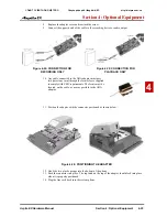
3. Set the dip switches on the CTA adapter to the required position.
•
The DSW settings are 1 = on, 2-8 = off for a PC connection or 1 and 2 = on, 3-8 = off for a
printer connection (factory setting is for a PC connection).
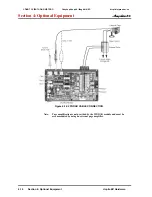
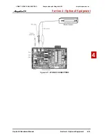
Figure 4-29: RECORDING DIP SWITCH SETTINGS
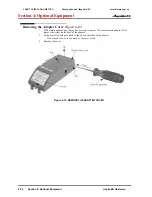
4. Position the adapter with the connector positioned as shown below.
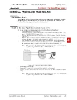
Figure 4-30: POSITIONING THE ADAPTER
5. Hook the two plastic prongs into the bottom of the phone.
6. Push the connector into place. The latch on the top of the adapter should lock into place when
it is properly positioned.
7. Change system programming (15-02-19) to match the CTA module dip switch settings.
8. Plug the line cord back into the system phone.
The RS-232 cable connected to the CTA must pass through (no
turns) the ferrite sleeve supplied to comply with EMC require-
ments.
System Programming
°
Program 15-02-19 : Multi-Line Telephone Basic Data Setup - CTA Data Commu-
nication Mode
Select ‘0’ if the dip switch settings are set to PC connection or select ‘1’ if printer con-
nection is selected on the CTA adapter.
°
Program 15-02-20 : Multi-Line Telephone Basic Data Setup - Baud Rate for CTA
Port
Set the baud rate to be used by the CTA (0=4800, 1=9600, 2=19200).
CÔNG TY VIỄN THÔNG VIỆT PRO
Chuyên phân phối tổng đài NEC
http://vietpro.com.vn

