Section 2: PCB Installation and Startup
Aspila EX Hardware Manual
Section 2: PCB Installation and Startup
2-45
2
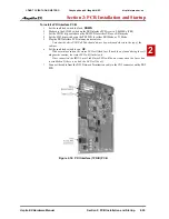
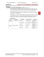
VoIP (16VOIPU) PCB
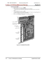
(Figure 2-19)
The VoIP PCB is used for converting the RTP (Real Time Transfer Protocol) packets via the IP net-
work and PCM highway. The IP telephones are connected directly to the IP bus. When IP phones need
to be connected to a conventional PCM-based digital circuit, this PCB converts the IP packet signal
into a PCM signal format and connects to the PCM time division switch.
The 16VOIPU PCB is required in order for IP telephones to communicate with non-VoIP Aspila EX
phones, as well as to place or receive outside calls.
The 16VOIPU PCB provides:
•
16VOIPU PCB provides up to 16 channels
•
Connector for the VOIPDB daughter board (providing an additional 16 channels)
•
1 PCB status LED
•
1 run/block switch
A maximum of 6 PCBs per system are allowed, providing 96 channels (with the daughter board, 192
channels), it can be plugged into any universal slot.
If a separate software hub is used (and not the 8SHUBU PCB), it should be a 100Base/full duplex hub.
To avoid network problems and to ensure good voice quality, do not use a Repeater Hub/10Base.
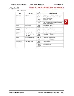
LED Indications
LED
Function
LED
Status
Operation Status
Comments
DB Run
Status of 16VOIPDB
Red
16VOIPDB is operating normally.
Off
16VOIPDB is not functioning
correctly.
RTP
Session
Status
Status of RTP Session
Red
RTP session is established.
LED is on if one
of the channels is
established.
Off
RTP session is not established.
PCMCIA
Status of PCMCIA
Slot
Red
PC-ATA card installed.
Off
PC-ATA card not installed.
LED A
(On CN4)
Data Transmission
and Reception
On
Data is being transmitted or
received.
LED B
(On CN4)
Status of Link
On
Link is established.
CÔNG TY VIỄN THÔNG VIỆT PRO
Chuyên phân phối tổng đài NEC
http://vietpro.com.vn


