System Overview 1-3
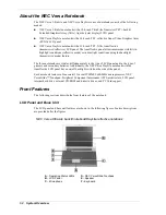
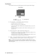
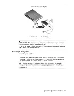
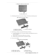
NEC Versa DayLite transflective notebook
A
– LCD Panel
E
– Speaker
B
– LCD Backlight On/Off Switch
F
– Keyboard
C
– Microphone
G
– Operating Status LEDs
D
– NEC VersaGlide Touchpad
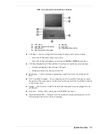
!
LCD Panel — Provides a high-resolution display for sharp visuals on the notebook.
—
Adjust the LCD panel by tilting it up or down.
—
Adjust the LCD panel brightness by pressing the
Fn-F8
and
Fn-F9
functions keys.
!
LCD Panel Backlight On/Off Switch (NEC Versa DayLite transflective notebook only)
—
Provides backlighting to the reflective LCD panel.
—
Switch up position is on, down position is off.
!
Microphone — Allows recording of monophonic sound directly into the notebook hard
drive.
!
NEC VersaGlide Touchpad — Move a fingertip over the VersaGlide Touchpad to control
the position of the mouse pointer. Use the selection buttons below the VersaGlide Touchpad
to select menu items.
!
Speaker — Provides mono sound for the notebook when speakers are not plugged into the
speaker jack.
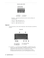
!
Keyboard — 86 keys with a country-specific QWERTY-key layout.
!
Operating Status LEDs — Informs user of the notebook's current operating status. See the
following figure and list for each icon's meaning.
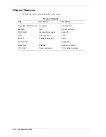
Summary of Contents for DayLite Series
Page 42: ...3 Disassembly and Reassembly Required Tools and Equipment Disassembly Reassembly ...
Page 58: ...5 Illustrated Parts Breakdown Illustrated Parts Breakdown Parts List ...
Page 65: ...7 Troubleshooting Problem Checklist Startup Problems Diagnostics ...
Page 73: ...8 NEC Computers Information Services Service and Support Functions Technical Support ...
Page 76: ...9 Specifications System Components Memory Map Interrupt Controllers ...