background image

NEC AUSTRALIA Pty. Ltd.

Service Manual

Oct. 2004

Color Television

CHASSIS : CP-185A (AUSTRALIA)

Model : 

DTA-14V4THS

DTA-20V4THS

DTA-21V4THS

NEC Model : N3481

N4881

FS572

Specification

S/M No. : TCP185AEF0

Version

Pal multi system

TV Standard

PAL-SECAM B/G, D/K, H, I/I (NTSC : AV Only)

Sound system

Mono

* 1 Speaker

Power consumption

14":49W / 20":60W / 21" 68W

Speaker

3W 8 Ohm o 7.5W 8 Ohm

Teletext system

Teletext

Aerial Input

75 Ohm unbalanced

Channel coverage

off-air channels, S-cable channels and hyperband

Tuning system

Ferquency synthesiser tuning system

14":34cm

Visual screen size

20’:48cm
21":51cm

Channel indication

On screen display

Program selection

100 Programmes

RCA jack : Audio input and Vidio input & A/V 
output(monitor out)

Auxiliary Outpup Terminal

Audio - Video jack on front of cabinet in common
connection with rear RCA jack 
Headphone jack on front of cabinet

Remote control

R-44N08 

AA Battery type

Summary of Contents for DTA-14V4THS

Page 1: ...W 8 Ohm o 7 5W 8 Ohm Teletext system Teletext Aerial Input 75 Ohm unbalanced Channel coverage off air channels S cable channels and hyperband Tuning system Ferquency synthesiser tuning system 14 34cm...

Page 2: ...TRUCTIONS 4 1 Service mode 4 2 Microcontroller configuration 4 3 TV SET Alignment 4 5 SCHEMATIC DIAGRAM 6 EXPLODED VIEW 7 PRINTED CIRCUIT BOARD 8 SERVICE PARTS LIST 9 FUNCTIONAL DESCRIPTION 1 6 IC DES...

Page 3: ...lass fragments will be violently expelled 2 If any Fuse in this TV receiver is blown replace it with the FUSE specified in the Replacement Parts List 3 When replacing a high wattage resistor oxide met...

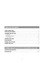
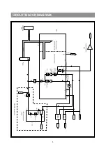
Page 4: ...3 CIRCUIT BLOCK DIAGRAM ISO1 S W IC ISO2 S W IC Monitor Out Audio Monitor Out Video I602 I702...

Page 5: ...ocal key board When changed NEW EEPROM I702 Remocon key code was changed Daewoo In order to change NEC Remocon key code do above procedure TV set Alignment 1 G2 alignment Set TV in NORMAL I mode TV in...

Page 6: ...litude Shift S Correction and Slope to compensate for vertical distortion 5 Horizontal picture centering Adjust H Shift to have the picture in the center of the screen 7 AGC Adjust the antenna signal...

Page 7: ...6...

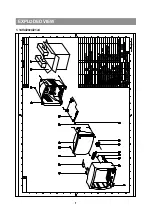
Page 8: ...7 7 EXPLODED VIEW 1 14V4 20v4 21v4...

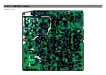
Page 9: ...8 PCB MAIN CP 185A...

Page 10: ...PTITE TT2 TRS 4X14 MFZN BK M492 4854941423 BUTTON POWER FR ABS GY M681 4856812001 TIE CABLE NYLON66 DA100 M683 4856812001 TIE CABLE NYLON66 DA100 M684 4856816300 CLAMP WIRE NYLON 6 V0 SP01A 7178301011...

Page 11: ...TT2 RND 3X8 MFZN I802 1LTV817C IC PHOTO COUPLER LTV 817C I804 1LP295033 IC REGULATOR LP2950 3 3V I805 1S7805P1C IC REGULATOR S7805PIC 5 0V 1 0A TO 220F 3SL S LEAD I901 PTC3SW1100 HEAT SINK ASS Y 1TDA...

Page 12: ...CERA 2KV B 1000PF K TAPPING ZZ200 PTMPJBE040 PCB MAIN M 10 AS DTA 21V4THS 10 2TM18006BE TAPE MASKING 6 2X500 E001 4856310300 EYE LET BSR T0 2 R1 6 E002 4856310300 EYE LET BSR T0 2 R1 6 E003 4856310300...

Page 13: ...P C121 CEXF1H100V C ELECTRO 50V RSS 10MF 5X11 TP C320 CEXF1H101V C ELECTRO 50V RSS 100MF 8X11 5 TP C354 CMXM2A104J C MYLAR 100V 0 1MF J TP C355 CMXM2A104J C MYLAR 100V 0 1MF J TP C403 CMXM2A104J C MYL...

Page 14: ...CTRO 25V RSS 100MF 6 3X11 TP C819 CEXF1E470V C ELECTRO 25V RSS 47MF 5X11 TP C820 CEXF1C101V C ELECTRO 16V RSS 100MF 6 3X11 TP C822 CMXM2A104J C MYLAR 100V 0 1MF J TP C832 CEXF1H100V C ELECTRO 50V RSS...

Page 15: ...ING 3M 232 MAP C 6 2X2000M A001 4859810493 PCB MAIN 246X246 D1B C350 CCZB1H103K C CERA HIKB 50V 0 01MF K AXIAL C501 CCZF1H103Z C CERA 50V F 0 01MF Z C515 CBZR1C222M C CERA 16V Y5R 2200PF M AXIAL C516...

Page 16: ...8 DIODE 1N4148 TAPPING D814 D1N4937G DIODE 1N4937G TAPPING D815 D1N4148 DIODE 1N4148 TAPPING D817 DUZ6R2BM DIODE ZENER UZ 6 2BM DA02 DUZ5R6BM DIODE ZENER UZ 5 6BM DA04 DUZ5R6BM DIODE ZENER UZ 5 6BM DA...

Page 17: ...NG J049 85801065GY WIRE COPPER AWG22 1 0 65 TIN COATING J050 85801065GY WIRE COPPER AWG22 1 0 65 TIN COATING J052 85801065GY WIRE COPPER AWG22 1 0 65 TIN COATING J053 85801065GY WIRE COPPER AWG22 1 0...

Page 18: ...AWG22 1 0 65 TIN COATING L101 5CPZ569K02 COIL PEAKING 5 6UH K AXIAL 3 5MM L303 5MC0000100 COIL BEAD HC 3550 L500 5CPZ829K02 COIL PEAKING 8 2UH K AXIAL 3 5MM L501 85801065GY WIRE COPPER AWG22 1 0 65 TI...

Page 19: ...ARBON FILM 1 6 1K OHM J R518 RD AZ273J R CARBON FILM 1 6 27K OHM J R520 RD AZ183J R CARBON FILM 1 6 18K OHM J R521 RD AZ391J R CARBON FILM 1 6 390 OHM J R522 RD AZ221J R CARBON FILM 1 6 220 OHM J R523...

Page 20: ...470J R CARBON FILM 1 6 47 OHM J R610 RD AZ162J R CARBON FILM 1 6 1 6K OHM J R710 RD AZ431J R CARBON FILM 1 6 430 OHM J R711 RD AZ681J R CARBON FILM 1 6 680 OHM J R712 5MC0000100 COIL BEAD HC 3550 R713...

Page 21: ...4Z2201F R METAL FILM 1 4 2 20K OHM F R843 RD AZ103J R CARBON FILM 1 6 10K OHM J R901 RD AZ102J R CARBON FILM 1 6 1K OHM J R902 RD AZ102J R CARBON FILM 1 6 1K OHM J R903 RD AZ102J R CARBON FILM 1 6 1K...

Page 22: ...ier and AGC circuit The nominal frequency of the demodulator is tuned to the required frequency 5 5 6 0 6 5 MHz by means of a calibration circuit which uses the clock frequency of the microcontroller...

Page 23: ...hen signals with a high chroma to burst ratio are received The ACL circuit is designed such that it only reduces the chroma signal and not the burst signal This has the advantage that the colour sensi...

Page 24: ...automatic adjustment of the Vg2d voltage during the production of the TV receiver During switch off of the TV receiver a fixed beam current is generated by the black current control circuit This curre...

Page 25: ...he video processor pin 28 has multiple functions and provides in this applicationbus Deemphasis time constant Audio monitor output External AM input Deemphasis time constant The time constant is given...

Page 26: ...pull mode can be used for output only Both sinking and sourcing is active which leads to steep slopes The levels are 0 and Vddp the supply voltage 3 3Volts High impedance This mode can be used for inp...

Page 27: ...ns via resistors R350 and R351 The differential input voltage is compared with the output current through the deflection coils measured as voltage across R302 which provides internal feed back informa...

Page 28: ...Continuous Cathode Calibration white point and black level off set adjustment so that the colour temperature of the dark and the bright parts of the screen can be chosen independently Linear RGB or YU...

Page 29: ...colour palette Globally selectable scan lines per row 9 10 13 16 and character matrix 12x10 12xl3 12x16 VxH Fringing Shadow selectable from N S E W direction Fringe colour selectable Meshing of defin...

Page 30: ...al time capture and decoding for WST Teletext in Hardware to enable optimised microprocessor throughput 10 pages stored On Chip lnventory of transmitted Teletext pages stored in the Transmitted Page T...

Page 31: ...10 10 10 IC DESCRIPTION APPENDIX...

Page 32: ...switching input VssC P 9 digital ground for controller core and peripheral LED 1 10 port 0 5 8mA current sinking capability LED 2 11 port 0 6 8mA current sinking capability VSSA 12 analog ground of t...

Page 33: ...r TV processor CVBS Y 42 external CVBS Y input CHROMA 43 chrominance input SVHS AUDOUT 44 audio out INSSW2 45 2nd RGB insertion input R2IN 46 2nd R input G2IN 47 2nd G input B2IN 48 2nd B input BCLIN...

Page 34: ...13 13 13 IC DESCRIPTION APPENDIX TDA 9361 OR TDA9381...

Page 35: ...jection Low turn on off pop Stand by mode Decription The device TDA7267A is a new technology Mono Audio Amplifier in Power DIP package specifically designed for TV application Thanks to the fully comp...

Page 36: ...on Board Square heat Sink vs Copper Area Example of heatsink using PC board copper Symbol Parameter Value unit Vs Operating Supply Voltage 18 V Io Output Put Peak Current 1 5 A Top Operating Temperatu...

Page 37: ...ICAL CHARACTERISTICS Tamb 25 C Vs 14 5V RL 8 f 1KHz nuless otherwise specified APPLICATION HINTS For 14 5V supply and 8 speaker application its maximum power dissipation is about 1 8W Assumming that m...

Page 38: ...17 17 3 STV9302A 17 IC DESCRIPTION APPENDIX fi...

Page 39: ...18 18 IC DESCRIPTION APPENDIX...

Page 40: ...19 19 IC DESCRIPTION APPENDIX...

Page 41: ...20 20 IC DESCRIPTION APPENDIX...

Page 42: ...21 21 IC DESCRIPTION APPENDIX...

Page 43: ...22 22 IC DESCRIPTION APPENDIX...

Page 44: ...23 23 IC DESCRIPTION APPENDIX...

Page 45: ...24 IC DESCRIPTION APPENDIX...

Page 46: ...25 IC DESCRIPTION APPENDIX...

Page 47: ...26 IC DESCRIPTION APPENDIX...

Page 48: ...27 IC DESCRIPTION APPENDIX...

Page 49: ...28 IC DESCRIPTION APPENDIX...

Page 50: ...29 IC DESCRIPTION APPENDIX...

Page 51: ...30 IC DESCRIPTION APPENDIX...

Page 52: ...31 IC DESCRIPTION APPENDIX...

Page 53: ...l Features Typical bandwidth of 5 5 MHz for an output signal of 60 Vpp High slew rate of 900V s No external components requireds Very simple application Single supply voltage of 200V Internal referenc...

Page 54: ...ses a bi directional data bus and serial clock The memory carries a built in 4 bit unique device type identifier code 1010 in accordance with the I2C bus definition Serial Clock SCL The SCL input is u...

Page 55: ......

Reviews: