


-16-
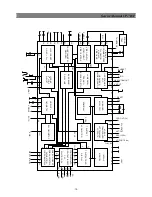
Service Manual CP-785F
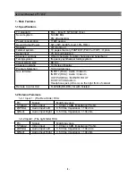
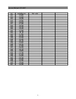
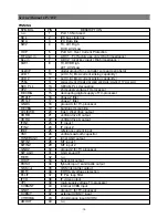
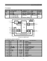
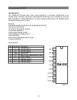
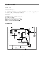
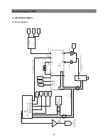
SYMBOL
PIN DESCRIPTION
n.u.
1
Port 1.3 Not used.
SCL
2
I2C bus clock line
SDA
3
I2C Data line
SW2 4
TV,
AV1:High
DVD, AV2:Low
OCP
5
Port 3.0 : Over Current Protection
RF AGC in
6
ADC 1 : For factory use only ( High impedance )
Key-in
7
ADC 2 : local key input ( High impedance )
S/W1 8
TV,DVD:High
AV1, AV2:Low
VssC/P
9
digital ground for -controller core and peripheral
LED 1
10
port 0.5 ( 8mA current sinking capability )
LED 2
11
port 0.6 ( 8mA current sinking capability )
VSSA
12
analog ground of teletext decoder and digital ground of TV processor
SEC PLL
13
SECAM PLL decoupling
VP2
14
2nd supply voltage TV-processor
DECDIG
15
decoupling digital supply of TV-processor
PH2LF 16
phase-2
filter
PH1LF 17
phase-1
filter
GND3
18
ground 3 for TV-processor
DECBG 19
bandgap
decoupling
AVL/EWD
20
East / West drive output
VDRB
21
vertical drive B output
VDRA
22
vertical drive A output
IFIN1
23
IF input 1
IFIN2
24
IF input 2
IREF
25
reference current input
VSC
26
vertical sawtooth capacitor
TUNERAGC
27
tuner AGC output
SIFIN1
28
SIF input 1
SIFIN2
29
SIF input 2
GND2
30
ground 2 for TV processor
SIF AGC
31
AGC sound IF
REF0 32
n.u.
HOUT 33
horizontal
output
FBISO
34
flyback input / sandcastle output
QSS out
35
QSS intercarrier output
EHT0 36
EHT/Overvoltage
protection
PLLIF
37
IF PLL loop filter
IFVO
38
IF video output
VP1
39
main supply voltage TV-processor
CVBSINT
40
internal CVBS input
GND1
41
ground 1 for TV-processor
CVBS/Y
42
external CVBS/Y input
CHROMA
43
chrominance input (SVHS)
AMOUT
44
n.u.
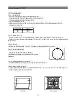
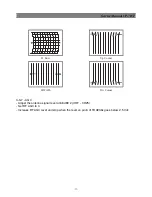
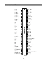
PINNING
Summary of Contents for DTE-29U1TH
Page 67: ...Service Manual CP 785F 66 7 Exploded view ...
Page 68: ...Service Manual CP 785F 67 8 PCB Layout 8 1 Main PCB ...
Page 69: ...Service Manual CP 785F 68 8 2 AV PCB ...
Page 70: ... 69 Service Manual CP 785F 9 Circuit Diagram ...
Page 71: ...NEC Corporation 7 1 SHIBA 5 CHOME MINATO KU TOKYO 108 8001 JAPAN ...


