
-2-
Service Manual CP-785F
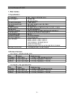
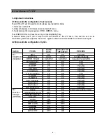
1-1 Specifications
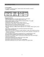
1 - Main Features
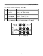
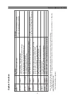
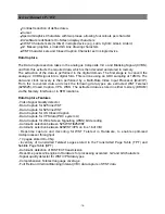
1-2 External Teminals
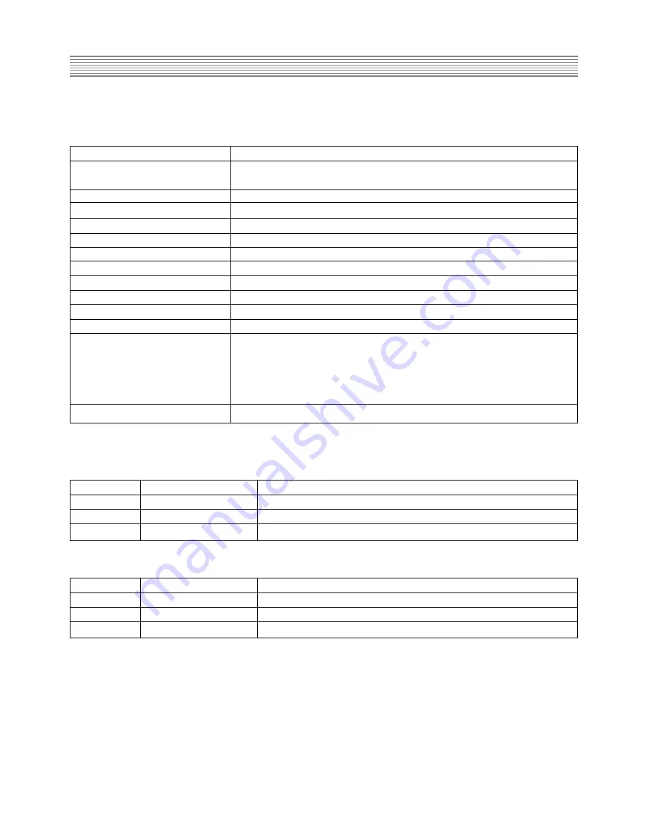
1-2-1 Input 1 : (The Rear Side) RCA
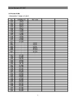
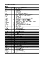
TV standard
PAL, - B/G, H, NTSC(AV Only)
Sound system
NICAM B/G
FM 2Carrier B/G
Power consumption
116W approx.
Sound Output Power
5W x 5W (at 60% mod, 10% THD)
Speaker
7W 8 ohm x 2
Teletext system
10 pages memory FASTEXT (FLOF or TOP) : Option
Aerial input
75 ohm unbalanced
Channel coverage
Off-air channels, S-cable channels and hyperband
Tuning system
frequency synthesiser tuning system
Visual screen size
68 Cm
Channel indicatio
On Screen Display
Program Selection
100 programmes
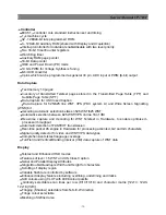
Aux. terminal
INPUT1(RCA) : Audio / Video In.
INPUT2(RCA) : Audio / Video In
OUTPUT(RCA) : MONITOR OUT
DVD:Y/Cr/Cb/Audio in
Headphone jack (3.5 mm) on the right front of cabinet
Remote Control Unit
R-44N08(RD-D90) for with Teletext
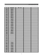
Pin
Signal
Matching value
1(Yellow)
Video Input
1.0 Vpp+/- 3dB, Impedance 75 ohm
2(White)
Audio Input Left
0.5 Vrms, Impedance > 10k ohm
3(Red)
Audio Input Right
0.5 Vrms, Impedance > 10k ohm
1-2-2 Input2 : (The right Side) RCA
Pin
Signal
Matching value
1(Yellow)
Video Input
1.0 Vpp+/- 3dB, Impedance 75 ohm
2(White)
Audio Input Left
0.5 Vrms, Impedance > 10k ohm
3(Red)
Audio Input Right
0.5 Vrms, Impedance > 10k ohm
-2-
Summary of Contents for DTE-29U1TH
Page 67: ...Service Manual CP 785F 66 7 Exploded view ...
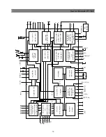
Page 68: ...Service Manual CP 785F 67 8 PCB Layout 8 1 Main PCB ...
Page 69: ...Service Manual CP 785F 68 8 2 AV PCB ...
Page 70: ... 69 Service Manual CP 785F 9 Circuit Diagram ...
Page 71: ...NEC Corporation 7 1 SHIBA 5 CHOME MINATO KU TOKYO 108 8001 JAPAN ...


