


-43-
Service Manual CP-785F
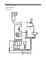
5-9 TV start-up, TV normal run and stand-by mode operations
5-9-1 TV start-up operations
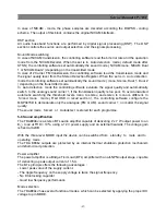
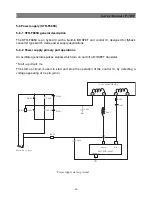
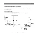
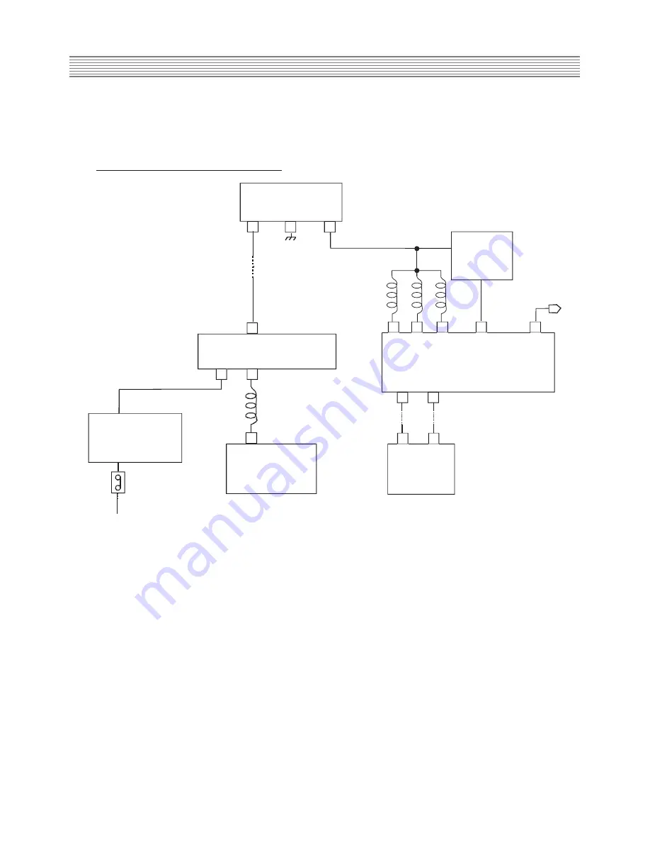
* Schematic diagram for start-up operations
I823 REG 3.3V
IN
G N D
O U T
1
2
3
RESET
P U L S E
CIRCUIT
IN
O U T
63
60
54
56
61
L511
L510
L512
Vddc VddA
Reset N
Power
I501
M I C R O C O N T R O L L E R P A R T
SCL
SDA
3
2
5
6
3
4
2
D
I801 MOSFET AND
C O N T R O L I C
I702
E E P R O M
SW801
P O W E R S W I T C H
M A I N A C V O L T A G E
D801... D804
(GRAETZ BRIDGE)
L801
T8 0 1 SM PS T RA NSF ORM ER
12
8V
Vddp
Start-up operations
* TV start-up and microcontroller initialization
- When SW801 power switch is pushed, main AC voltage is applied to T801 transformer (after
rectification by D801...D804 diodes). Then, T801 SMPS transformer starts operating and
supplies DC voltage to I823 (3.3V regulator).
- This regulator provides 3.3V DC voltage to I501 microcontroller power supply pins (pins 54,
56, 61) and to the reset pulse circuit which provides reset pulse to I501 microcontroller reset
pin (pin 60).
- Then, the microcontroller starts its initialization. Its power pin (pin 63) is set to high which
allows delivery of power supply voltages (123V, 8V, 5V...). At this step, all IC s start working
but no picture appears on screen: I501 IC doesn t provide horizontal drive voltage.
- Then, the microcontroller consults I702 EEPROM via I2C bus to know the last TV set mode
(normal run mode or stand-by mode ) before switching off.
Summary of Contents for DTE-29U1TH
Page 67: ...Service Manual CP 785F 66 7 Exploded view ...
Page 68: ...Service Manual CP 785F 67 8 PCB Layout 8 1 Main PCB ...
Page 69: ...Service Manual CP 785F 68 8 2 AV PCB ...
Page 70: ... 69 Service Manual CP 785F 9 Circuit Diagram ...
Page 71: ...NEC Corporation 7 1 SHIBA 5 CHOME MINATO KU TOKYO 108 8001 JAPAN ...


