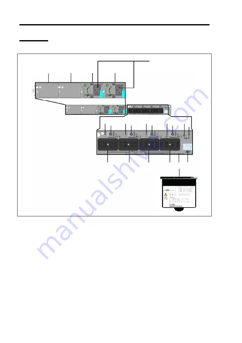
2-4 General Description
Rear View
1
Slot for power supply unit
Install the power supply unit that supplies DC power to the Module Enclosure.
The last digit indicates installation order. Slots 1 and 2 contain factory-installed power units.
Slots 3 and 4 are equipped with blank covers. Install the separately priced N8181-76F power
units into these slots to make the maximum configuration with four power supply units.
2
DC output lamp
Lights green when DC output is turned on. Goes off when DC output is turned off. The last
digit indicates the corresponding DC output port.
3
DC output switch
Press this switch to turn on or off the DC output. The last digit indicates the corresponding DC
output port.
4
DC output port
Supplies DC power to the target device. Connect the dedicated cable to this port. The last
digit indicates the port number.
5
Management port
Connector that accepts 100BASE-TX/10BASE-T interface.
1
-4
1
-3
1
-2
1
-1
2
-4
2
-3
2
-2
2
-1
3
-4
3
-3
3
-2
3
-1
7
6
4
-4
4
-3
4
-2
4
-1
8
5
9
Summary of Contents for EcoPowerGateway N8142-36F
Page 4: ......
Page 6: ......
Page 8: ......
Page 10: ... This page is intentionally left blank ...
Page 16: ...vi This page is intentionally left blank ...
Page 21: ...Notes on Using Your EcoPowerGateway 1 5 ...
Page 23: ...Notes on Using Your EcoPowerGateway 1 7 ...
Page 26: ...1 10 Notes on Using Your EcoPowerGateway ...
Page 29: ...Notes on Using Your EcoPowerGateway 1 13 ...
Page 38: ...1 22 Notes on Using Your EcoPowerGateway This page is intentionally left blank ...
Page 56: ...2 18 General Description This page is intentionally left blank ...
Page 136: ...A 2 Specifications This page is intentionally left blank ...


