Electra Elite
Issue 6
System Hardware Manual
5 - 49
4.9.3
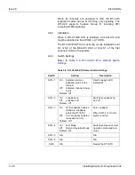
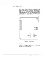
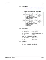
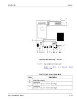
Switch Settings
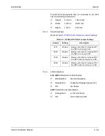
Refer to
Table 5-9 TLI(2)-U10 ETU Default Switch
Settings
.
4.9.4
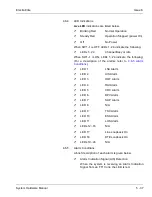
LED Indications
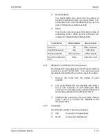
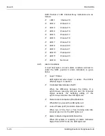
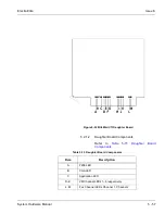
Live LED indications are listed below.
Blinking Red
Normal Operation
Steady Red
Operation Stopped (power On)
Off
No Power
CH 1 ~ CH 2 indications are listed below.
Steady Red
Lines 1~2 busy
Off
Lines 1~2 idle
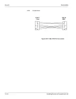
4.9.5
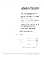
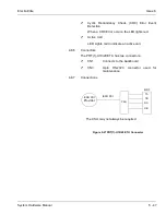
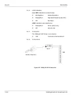
Connectors
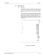
The TLI(2)-U10 ETU has one connector:
CN1
Connects to the backboard
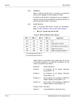
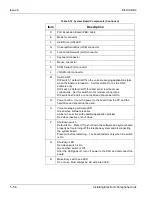
Table 5-9 TLI(2)-U10 ETU Default Switch Settings
Switch
Setting
Description
SW101
When lines provided by this unit
are used for back-to-back
connections, set to Type V.
When connection is to a Central
Office, set to Type I.
Default: Type V
Switch Type I
or Type V for
Line 1
SW201
When lines provided by this unit
are used for back-to-back
connections, set to Type V.
When connection is to a Central
Office, set to Type I.
Default: Type V
Switch Type I
or Type V for
Line 2
Summary of Contents for Electra Elite 192
Page 2: ...SYSTEM HARDWARE MANUAL Stock Number 750363 Issue 6 Series 6000 192 ...
Page 3: ......
Page 5: ......
Page 9: ...THIS PAGE INTENTIONALLY LEFT BLANK ...
Page 10: ...Regulatory Information ...
Page 11: ......
Page 20: ......
Page 52: ...Issue 6 Electra Elite xxxii List of Tables THIS PAGE INTENTIONALLY LEFT BLANK ...
Page 73: ...Electra Elite Issue 6 System Hardware Manual 1 21 THIS PAGE INTENTIONALLY LEFT BLANK ...
Page 74: ...Issue 6 Electra Elite 1 22 Introduction ...
Page 96: ...Issue 6 Electra Elite 2 22 System Specifications ...
Page 104: ...Issue 6 Electra Elite 3 8 Hardware Requirements THIS PAGE INTENTIONALLY LEFT BLANK ...
Page 213: ...Electra Elite Issue 6 System Hardware Manual 5 67 Figure 5 39 FMS 8 U10 ETU ...
Page 336: ...Issue 6 Electra Elite 7 54 Installing Optional Equipment THIS PAGE INTENTIONALLY LEFT BLANK ...
Page 368: ...Issue 6 Electra Elite A 4 Glossary of Abbreviations THIS PAGE INTENTIONALLY LEFT BLANK ...
Page 369: ...SYSTEM HARDWARE MANUAL NEC America Inc Issue 6 Series 6000 192 ...

