Issue 6
Electra Elite
5 - 58
Installing Electronic Telephone Units
5.2.1.3
Port Expansion Board
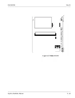
Refer to
Table 5-16 Port Expansion Board
Components
.
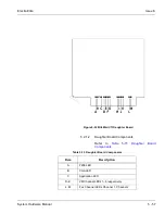
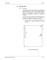
Figure 5-33 EliteMail CTI Port Expansion Board
Table 5-16 Port Expansion Board Components
Item
Description
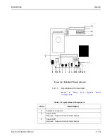
A
Backplane connector
B
MB LED – Always on when board is installed
C
MB switch – Do not use, leave On
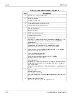
D
F206 LED
E
CGA Live LED
F~M
VM Channels 9~16, respectively
Summary of Contents for Electra Elite 192
Page 2: ...SYSTEM HARDWARE MANUAL Stock Number 750363 Issue 6 Series 6000 192 ...
Page 3: ......
Page 5: ......
Page 9: ...THIS PAGE INTENTIONALLY LEFT BLANK ...
Page 10: ...Regulatory Information ...
Page 11: ......
Page 20: ......
Page 52: ...Issue 6 Electra Elite xxxii List of Tables THIS PAGE INTENTIONALLY LEFT BLANK ...
Page 73: ...Electra Elite Issue 6 System Hardware Manual 1 21 THIS PAGE INTENTIONALLY LEFT BLANK ...
Page 74: ...Issue 6 Electra Elite 1 22 Introduction ...
Page 96: ...Issue 6 Electra Elite 2 22 System Specifications ...
Page 104: ...Issue 6 Electra Elite 3 8 Hardware Requirements THIS PAGE INTENTIONALLY LEFT BLANK ...
Page 213: ...Electra Elite Issue 6 System Hardware Manual 5 67 Figure 5 39 FMS 8 U10 ETU ...
Page 336: ...Issue 6 Electra Elite 7 54 Installing Optional Equipment THIS PAGE INTENTIONALLY LEFT BLANK ...
Page 368: ...Issue 6 Electra Elite A 4 Glossary of Abbreviations THIS PAGE INTENTIONALLY LEFT BLANK ...
Page 369: ...SYSTEM HARDWARE MANUAL NEC America Inc Issue 6 Series 6000 192 ...

