Electra Elite IPK II
Document Revision 3
System Hardware Manual
7 - 5
___________________________________________________________________________________
___________________________________________________________________________________
6.2
LED Indications
6.3
Setting Up PGD(2)-U10 ADP Connections
When the PGD(2)-U10 ADP is to be wall mounted, all the cable connections
should be made first.
For the module to ID correctly after setting the jumpers, set the circuit to zero
for the module port in Program 10-03-01 prior to connecting the line cord to
the PGD(2)-U10 ADP.
1.
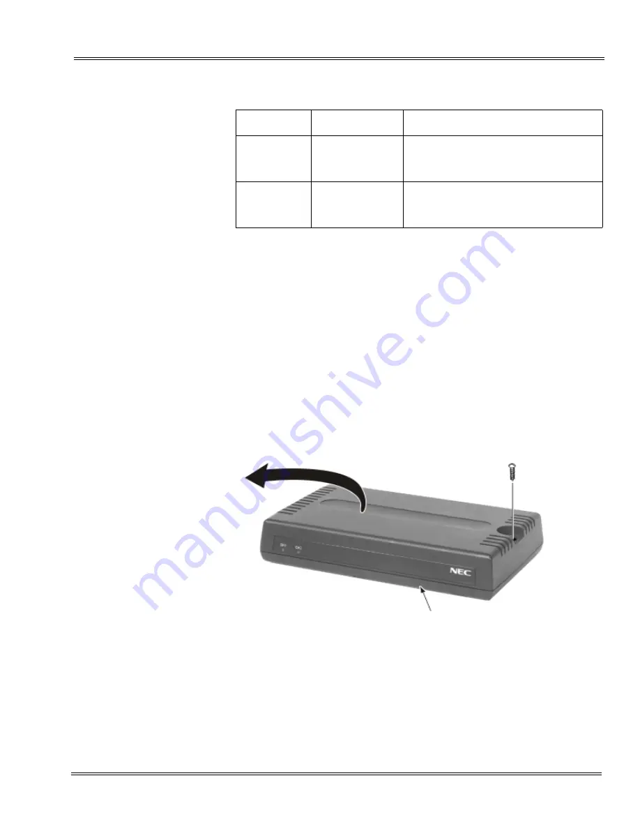
Remove the screw from the front of the PGD(2)-U10 ADP.
2.
Using a screwdriver, break out the plastic piece covering the cable hole.
LED
Indication
Note
LED 1
Green LED
when CH1 in
use.
Flashing green LED indicates dip switch
setting and programming for CH1 are in
conflict.
LED 2
Green LED
when CH2 in
use.
Flashing green LED indicates dip switch
setting and programming for CH2 are in
conflict.
Figure 7-4 Remove Cover from PGD(2)-U10 ADP
Module
Summary of Contents for ELECTRA ELITE IPK II
Page 2: ......
Page 3: ...SYSTEM HARDWARE MANUAL INT 1076 IPK II DOCUMENT REVISION 3 VERSION 2000...
Page 4: ......
Page 6: ......
Page 10: ...THIS PAGE INTENTIONALLY LEFT BLANK...
Page 641: ...SYSTEM HARDWARE MANUAL NECUnified Solutions Inc Document Revision 3...
Page 642: ......


