Electra Elite IPK II
Document Revision 3
System Hardware Manual
6 - 19
___________________________________________________________________________________
___________________________________________________________________________________
4.3.2
Installation
Turn system power off, and install the EXP-U( ) ETU in the
CPU/EXP slot of the expansion KSU.
4.3.3
Connectors
The following connectors are included:
J
CN1
Connects to the backplane.
J
CN2
Connected to CN3 on the CPUII( )-U10 ETU or
CN3 on EXP-U( ) ETU (installed in the first
expansion cabinet) using an expansion cable.
J
CN3
Connected to CN2 on the EXP-U( ) ETU
installed in the third expansion cabinet using the
expansion cable.
Not used when the EXP-U( ) ETU is installed in
the last Expansion KSU.
4.3.4
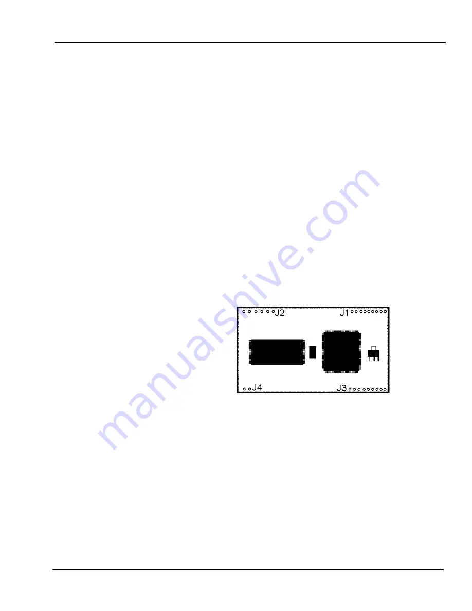
MOD-U10 Unit
This unit is installed on the CPUII( )-U10 ETU to provide a modem
and must be installed in connectors J1, J2, J3, and J4.
The MOD-U10 Unit pins and the sockets of the CPUII( )-U10 ETU
are labeled alike. Line up MOD unit connector J1 with CPUII ETU J1
and MOD unit J2 with CPUII ETU J2, and carefully plug in the unit.
Figure 6-9 MOD-U10 Unit
Summary of Contents for ELECTRA ELITE IPK II
Page 2: ......
Page 3: ...SYSTEM HARDWARE MANUAL INT 1076 IPK II DOCUMENT REVISION 3 VERSION 2000...
Page 4: ......
Page 6: ......
Page 10: ...THIS PAGE INTENTIONALLY LEFT BLANK...
Page 641: ...SYSTEM HARDWARE MANUAL NECUnified Solutions Inc Document Revision 3...
Page 642: ......


