Electra Elite IPK II
Document Revision 3
System Hardware Manual
7 - 7
___________________________________________________________________________________
___________________________________________________________________________________
4.
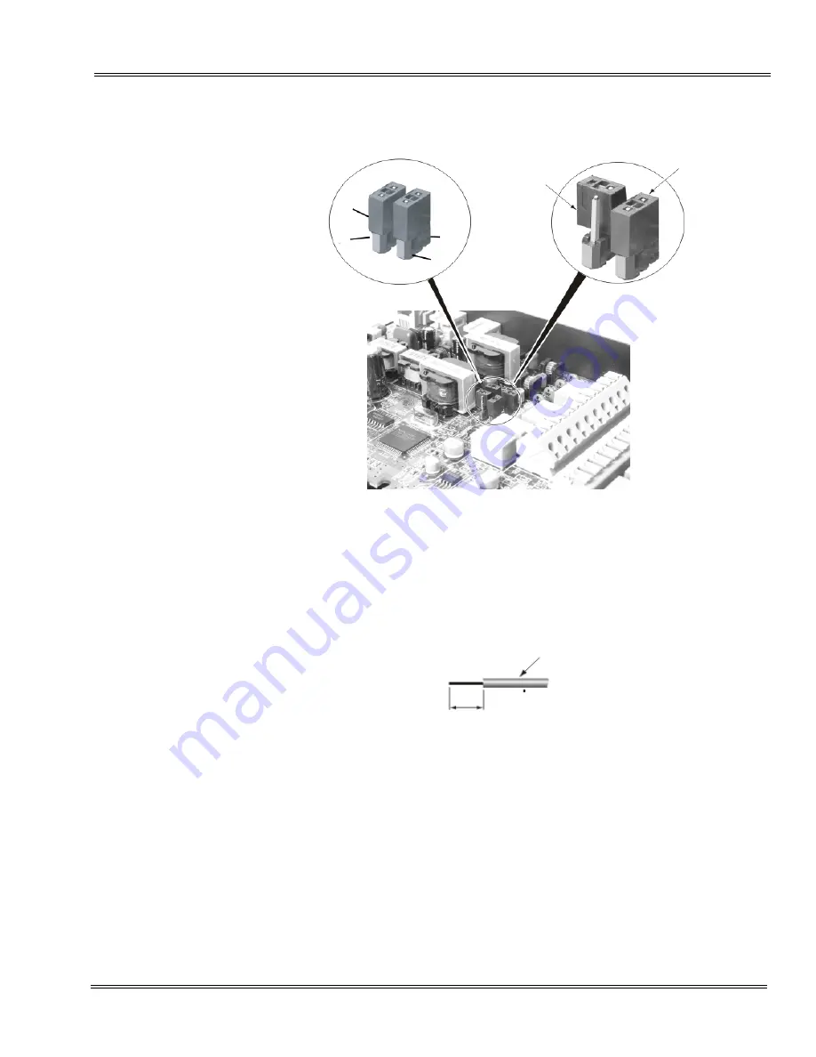
Strip one end of the cable to be connected to the control relay or door
box so that approximately 1/4” (8 mm) of bare wire is exposed.
5.
Insert the cable in the proper CN4 or CN5 location while holding down
the lock button with a flat-head screwdriver. After the cable is in place,
release the lock button.
Refer to the specific function being connected for more detail on
PGD(2)-U10 ADP connections.
Figure 7-6 Jumper Settings
Short setting
Open setting
S6
S3
S4
S5
Cable
8mm
Summary of Contents for ELECTRA ELITE IPK II
Page 2: ......
Page 3: ...SYSTEM HARDWARE MANUAL INT 1076 IPK II DOCUMENT REVISION 3 VERSION 2000...
Page 4: ......
Page 6: ......
Page 10: ...THIS PAGE INTENTIONALLY LEFT BLANK...
Page 641: ...SYSTEM HARDWARE MANUAL NECUnified Solutions Inc Document Revision 3...
Page 642: ......


