___________________________________________________________________________________
3 - 36
System Specifications
___________________________________________________________________________________
Document Revision 3
Electra Elite IPK II
5.9.4
External Tone Ringer/Night Chime Output
J
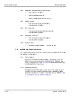
Output Power: -10 dBm
J
Output Impedance:600
Ω
J
Relay Contact Rating:500 mA, 24 Vdc
5.9.5
SMDR Output
J
Female Connector (System Output):
Standard DB-9 (straight)
5.9.6
PC Connection
J
Female Connector (System Input/Output):
Standard DB-9 (straight)
5.9.7
ACD/MIS Connector
J
Female Connector (System Output):
Standard DB-9 (straight)
5.9.8
Relay Contact
J
All Relay Contact Ratings:
500 mA, 24 Vdc
5.10
Audible and Visual Indications
The tables in this section provide the audible and visual indications used in the
Electra Elite IPK II systems.
5.10.1
Tone Patterns
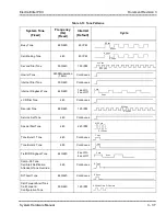
Tones are used in the Electra Elite IPK II systems to inform the
station user of various system functions such as, dial tone, busy
tone, or ringback tone.
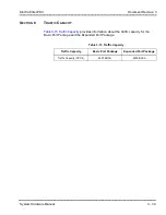
Table 3-14 Tone Patterns
lists the frequency
and the pattern for these tones.
5.10.2
LED Flash Patterns
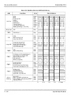
The Electra Elite IPK II system has 2-color LEDs. Green is used
primarily for I-Use conditions and for outside calls. Red is used
primarily for Other Use conditions and internal calls. Refer to
Summary of Contents for ELECTRA ELITE IPK II
Page 2: ......
Page 3: ...SYSTEM HARDWARE MANUAL INT 1076 IPK II DOCUMENT REVISION 3 VERSION 2000...
Page 4: ......
Page 6: ......
Page 10: ...THIS PAGE INTENTIONALLY LEFT BLANK...
Page 641: ...SYSTEM HARDWARE MANUAL NECUnified Solutions Inc Document Revision 3...
Page 642: ......


