background image

Summary of Contents for EXPRESS 5800 ES1400 SERIES Online

Page 1: ...EXPRESS5800 ES1400 SERIES ONLINE SERVICE GUIDE...

Page 2: ...system configuration customer data and operator control Since implementation by customers of each product may vary the suitability of specific product configurations and applications must be determine...

Page 3: ...os Configuration Utility which is used to configure SCSI devices in your system This chapter also provides information on system board jumper settings n Chapter 4 Upgrades and Options provides you wit...

Page 4: ...of life CAUTION Cautions indicate situations that can damage the system hardware or software Note Notes give important information about the material being described n Names of keyboard keys are print...

Page 5: ...etting Started Sheet The Getting Started Sheet provides several easy to follow steps to become familiar with your server documentation and to complete your installation successfully n Network Operatin...

Page 6: ...e ST or SJT 16 AWG 3 conductor provided with a molded on NEMA type 5 15 P plug cap at one end and a molded on cord connector body at the other end The cord length must not exceed 9 feet 2 7 meters Out...

Page 7: ...ystem warm or cool to room temperature before using it Keep the system away from magnetic forces Keep the system dry Do not wash the system with a wet cloth or pour fluid into it Protect the system fr...

Page 8: ...Using This Guide xv...

Page 9: ...1 System Overview n Overview n System Chassis n Power Supply n Peripheral Bays n Diskette Drive n System Board Features n System Security...

Page 10: ...e performance memory capacity and integrated I O provides a high performance environment for many server market applications These range from large corporations supporting remote offices to small comp...

Page 11: ...one slot shared with a PCI slot Embedded PC compatible support serial parallel mouse keyboard diskette and Plug and Play features n Integrated onboard Cirrus Logic CL GD5480 Super Video Graphics Array...

Page 12: ...pand fabricated metal structure The major system components are shown in this illustration A B C D E F G 1 2 4 3 A Removable Media Bays 3 B 1 44 MB 3 5 diskette drive C System Board D Speaker E Power...

Page 13: ...d States it is set to 230Vac for systems used in Europe Peripheral Bays The system supports a variety of standard PC AT compatible peripheral devices The chassis includes these peripheral bays n A 3 5...

Page 14: ...ector D DIMM slot 1 U Reserved E Reserved V PCI slots for add in boards F ATX power connector W ISA slots for add in boards G Reserved X VGA monitor port H Secondary IDE connector Y USB connectors I P...

Page 15: ...board contains three 168 pin DIMM sockets Memory is partitioned as three banks of SDRAM DIMMs each providing 72 bits of noninterleaved memory 64 bit main memory plus ECC Your system may include from 3...

Page 16: ...s using either 8 or 16 bit SCSI providing 10 MB s Fast 10 or 20 MB s Fast 20 throughput or 20 MB s Ultra or 40 MB s Ultra wide As implemented the controller attaches to a 68 pin 16 bit wide SCSI conne...

Page 17: ...Mbps and 100 Mbps networks capable of full or half duplex with back to back transmit at 100 Mbps The network status LEDs on the system board indicate n Transmit receive activity on the LAN n Valid li...

Page 18: ...orts two serial ports one parallel port diskette drive PS 2 compatible keyboard and mouse and integrated Real Time Clock RTC The system provides the connector interface for each port Serial Ports Both...

Page 19: ...by the manager system include over temperature and over voltage conditions fan failure or chassis intrusion Information on the Emergency Management Port EMP Console may be found in Appendix C of this...

Page 20: ...the correct password s For example n Enable the keyboard lockout timer so that the server requires a password to reactivate the keyboard and mouse after a specified time out period 1 to 120 minutes n...

Page 21: ......

Page 22: ...Setting Up Your System n Selecting a Site n Unpacking the System n Getting Familiar with the System n Making Connections n Setting the Line Voltage n Connecting the Power Cord n Powering On Your Syste...

Page 23: ...properly grounded outlet n Clean dust free and well ventilated Front and rear ventilating openings kept free of obstructions Away from sources of heat vibration or physical shock n Isolated from stro...

Page 24: ...ontainers prior to unpacking If the shipping boxes are damaged note the damage and if possible photograph it for reference After removing the contents of the containers keep the cartons and the packin...

Page 25: ...nd eject CD B Activity light CD ROM reader When lit CD ROM reader is in use C Activity light 3 inch diskette drive When lit diskette is in use D Eject button 3 inch diskette drive Press to eject diske...

Page 26: ...n mini DIN connector E COM1 COM1 serial port 9 pin connector F Printer 25 pin parallel port connector G COM2 COM2 serial port 9 pin connector H Green LAN status light When lit LAN is linked to network...

Page 27: ...o display and keyboard to configure the system You may remove them after running the System Setup Utility SSU For information on running the SSU refer to Appendix B of this User s Guide Refer the foll...

Page 28: ...g Up the System 2 7 115V H I J B A C D E F G A Keyboard B Mouse C Serial Port 1 COMM1 D Printer E Serial Port 2 COMM2 F LAN G Video Display VGA H PCI slots I Combo PCI ISA slot J ISA slot Making Conne...

Page 29: ...e setting for the power supply is correct To use the system with line source voltages between 200 and 230 VAC the line voltage selector switch on the power supply must be set to 230 If you set the swi...

Page 30: ...Setting Up the System 2 9 115V 115V 115V 230V A or B A Voltage selector switch set to 115 VAC B Voltage selector switch set to 230 VAC Setting the Line Voltage...

Page 31: ...be rated for the available AC voltage and have a current rating that is at least 125 of the current rating of the system n The power cord connector that plugs into the wall outlet must be terminated i...

Page 32: ...em board CPU module memory keyboard and most installed peripheral devices CAUTION Always allow POST to complete before powering down your system CAUTION The server management logic on your system boar...

Page 33: ...2 12 Setting Up the System...

Page 34: ...3 Configuring Your System n Configuring Your System n BIOS Setup Utility n Symbios Configuration Utility n Optional RAID Controller n Configuring System Board Jumpers...

Page 35: ...tility detects the SCSI host adapters on the system board Use this utility if you need to configure the SCSI controller in your system or to perform a SCSI disk format or verify disk operation on the...

Page 36: ...he top of the Main Menu lists the following selections Menu Bar Selections Menu Use Main Use this menu for basic system configuration Advanced Use this menu for setting the Advanced Features available...

Page 37: ...dow PAGE UP or PAGE DOWN Move cursor to next or previous page F5 or Select the previous value for the field F6 or or SPACE Select the next value for the field F9 Load default configuration values for...

Page 38: ...NTER Refer to Primary IDE Master and Slave Submenu Secondary IDE Master Press ENTER Refer to Secondary IDE Master and Slave Submenu Secondary IDE Slave Press ENTER Refer to Secondary IDE Master and Sl...

Page 39: ...e only for Type User Maximum Capacity N A Computed drive size This field is informational only for Type User Multi Sector Transfer Disabled 2 4 8 or 16 sectors Determines the number of sectors per blo...

Page 40: ...ey repeat Advanced Menu Feature Choices Description Your Setting Plug and Play OS No Yes Reset Configuration Data No Yes Select Yes if you want to clear the system configuration data during next boot...

Page 41: ...as a PCI bus master Latency Timer Default 0020h 0040h 0060h 0080h 00A0h 00C0h 00E0h Minimum guaranteed time in units of PCI bus clocks that a device may be master on a PCI bus PCI Device Slot 1 Slot...

Page 42: ...the port OS Controlled forces OS to configure the port Base I O Address 3F8 2F8 3E8 2E8 Selects the base I O address for COM port 2 Interrupt IRQ 3 IRQ 4 Selects the IRQ for COM port 2 Parallel Port...

Page 43: ...led Enable the Passive Release mechanism on PHOLD signal when PIIX4 is a PCI MASTER Security Menu Note Enabling the Supervisor Password field requires a password for entering Setup The passwords are n...

Page 44: ...Timer Disabled 1 min 2 min 5 min 10 min 20 min 1 hr 2 hr Period of key PS 2 mouse inactivity specified for secure mode to activate A password is required for secure mode to function Cannot be enabled...

Page 45: ...tion Your Setting System Management Press ENTER Refer to System Management Submenu Console Redirection Press ENTER Refer to Console Redirection Submenu Processor Retest Yes No Select Yes to have BIOS...

Page 46: ...cumentation EMP Access Mode Pre boot Only Always Active Disabled Pre boot Only EMP is only enabled during power down through power up to the end of POST Com 2 is returned to system use at the end of P...

Page 47: ...only Chassis Serial Number N A Information field only BMC Revision N A Information field only Primary HSBP Revision N A Information field only Console Redirection Submenu Feature Choices Description Y...

Page 48: ...ess ENTER Refer to Removeable Devices Submenu Boot Device Priority Submenu Use the up or down arrow keys to select a device then press the or keys to move the device higher or lower in the boot priori...

Page 49: ...the onboard Symbios SCSI bios treats CD ROMs as hard drives SCSI removable drives will also appear here 2 Other Bootable Device Covers all the boot devices that are not reported to the system BIOS thr...

Page 50: ...u bar to exit Choices Description Exit Saving Changes Exits after writing all modified Setup item values to CMOS Exit Discarding Changes Exits leaving CMOS unmodified Load Setup Defaults Loads default...

Page 51: ...tus Adapter Port Number IRQ Level Current Next Boot NVRAM Found SYM53C875 F800 11 On On Yes Change Adapter Status Press ENTER twice to change adapter Next Boot Status Adapter Boot Order Press ENTER to...

Page 52: ...Order Low to High Removable media support None CHS Mapping SCSI Plug and Play Mapping 2 Highlight the function you want to change and press ENTER You will be prompted to save changes when you exit the...

Page 53: ...able Media Devices Your Configuration Description Recommended Setting or Display Only Dev0 Dev1 Dev2 Dev3 Device Selections Press ENTER for menu Select device and press ENTER Sync Rate 10 Width bits 8...

Page 54: ...iped across three physical drives Parity protection is used for data redundancy This drive is used as the Hot Spare more _ _ The first four disks are as stated above the remaining disks are not part o...

Page 55: ...antistatic wrist strap attached to chassis ground The system board jumpers enable you to set specific operating parameters for your system A jumper is a small plastic encased conductor shorting plug t...

Page 56: ...lock Write Protect 2 3 Erase BIOS boot block is erasable and programmable D 9 10 Normal System attempts to boot using the BIOS stored in flash memory Recovery Boot 10 11 Recovery BIOS attempts a recov...

Page 57: ...1 Power off the system and remove the left panel as described in Chapter 4 of this guide 2 Check to ensure the system power cord is removed from the back of the system 3 Locate the position of the ju...

Page 58: ...per back to pins 1 2 6 Replace the left side panel and power on the system 7 Run the BIOS Setup Utility to check the configuration of your system Clearing and Changing the Passwords To clear and chang...

Page 59: ...the boot block incorrectly will prevent the system from booting Programming should only be done by a technically qualified person The procedure requires a special Boot Block Update Utility Contact you...

Page 60: ...Configuring Your System 3 27...

Page 61: ...EMI Shields and Filler Panels n Removable Media Devices n Removing the Top Cover n Installing the Top Cover n Removing the Removable Media Drive Bay n Installing the Removable Media Drive Bay n Remov...

Page 62: ...time you press the push button power on off switch on the front panel and your system powering down This is normal system operation and is required by the server management logic CAUTION Operating yo...

Page 63: ...d screwdriver n Small needle nose pliers n Pen or pencil n ESD workstation or antistatic wrist strap recommended Equipment Log Use the equipment log form located at the end of this manual to record th...

Page 64: ...oved Always replace the panels before powering on the system WARNING If you are removing the side panel after the system is set up you must first power off the system and all external devices Unplug t...

Page 65: ...ted in their respective slots and that all interior cables are properly connected 3 Insert the metal tabs on the top and bottom of the side panel into their slots on the chassis Slide the side panel f...

Page 66: ...round Replacing the Real time Clock Battery You may need to replace the real time clock battery because of its life span The battery Vendor Part CR2032 is a commodity part available through many vendo...

Page 67: ...figure 3 Gently push down on the screwdriver to lift the battery B 4 Remove the battery from its socket C 5 Dispose of the battery according to local ordinance 6 Remove the new lithium battery from it...

Page 68: ...late n back cover The SEPP packaged board includes n processor core with an integrated 16 KB primary L1 cache n secondary L2 cache The SECC2 packaged cartridge includes n processor core with an integr...

Page 69: ...the SEC cartridge upward out of the retention module and place it on a grounded static free surface or conductive foam pad A A Removing a Processor 4 Remove the two clips that secure the heat sink to...

Page 70: ...into the retention module Ensure that the alignment notch in the SEC cartridge fits over the plug in Slot 1 Push down firmly with even pressure on both sides of the top until the SEC cartridge is sea...

Page 71: ...ocessor upward out of the URM and place it on a grounded static free surface or conductive foam pad Removing a Processor 4 Remove the attachment clip Item A in Figure Processor Heat Sink Assembly belo...

Page 72: ...ocessor 10 Position the processor back into the URM Ensure that the alignment notch in the SEPP board fits over the plug in Slot 1 Push down firmly with even pressure on both sides of the top until th...

Page 73: ...rtridge upward out of the URM and place it on a grounded static free surface or conductive foam pad Removing a Processor 4 Remove the barbed spring pins Item A in Figure Processor Heat Sink Assembly b...

Page 74: ...ssor 10 Position the processor back into the URM Ensure that the alignment notch in the SEC cartridge fits over the plug in Slot 1 Push down firmly with even pressure on both sides of the top until th...

Page 75: ...hree sockets are populated the system board supports a maximum of 768 MB of memory with 256MB DIMMs A DIMM will always be installed in the right socket When you install additional DIMMs you must start...

Page 76: ...MB Slot 1 Slot 2 Slot 3 32 32 64 32 32 64 64 96 32 32 32 96 64 32 128 64 32 32 128 64 64 128 128 160 64 64 32 192 64 64 64 192 128 32 32 192 128 64 224 128 64 32 256 128 64 64 256 128 128 256 256 288...

Page 77: ...e edges remove it from its antistatic package 3 Position the DIMM so that the two notches in the bottom edge of the DIMM align with the keyed socket 2 3 1 Inserting Memory DIMMs 4 Insert the bottom ed...

Page 78: ...and remove the left side panel as described earlier in this chapter 2 Gently push the plastic ejector levers out and down to eject a DIMM from its socket 3 Hold the DIMM only by its edges being carefu...

Page 79: ...mplete the Plug and Play adapters are configured around the manually configured adapters without causing any resource conflicts ISA adapters can be Plug and Play ISA adapters that are not Plug and Pla...

Page 80: ...y board jumpers or switches as described in the documentation that comes with the option board 6 Refer to the documentation accompanying the option board for information on whether the board is a PCI...

Page 81: ...into the space that was occupied by the expansion slot cover 9 Reinstall the screw in the threaded hole Be sure to push the bracket slot up against the screw before you tighten it If this is not done...

Page 82: ...aining bracket screw 4 Hold the board at each end and carefully rock it back and forth until the edge connectors pull free Make sure that you do not scrape the board against other components 5 Remove...

Page 83: ...ector Each of these supports two devices for a total of four IDE devices n A first master device and a second slave device are supported on both the primary and secondary IDE connector The device conf...

Page 84: ...disk device consider the following n The system uses single ended SCSI host adapters and supports single ended or low Voltage Drives LVD drives n The hard disk SCSI address assignment is Bay Device S...

Page 85: ...3 5 inch drive bay to the rear of the chassis 5 Disconnect the power and signal cables from any installed drives 6 Swing the drive bay out of the chassis 7 Slide the drive bay towards the top of the...

Page 86: ...P9 4 HD2 Any available power connector 11 Swing the drive bay into the chassis and replace the three screws on the drive bay 12 Replace the left side panel and power on the system Configure the system...

Page 87: ...op of the chassis until the tabs on the bay are free from the chassis Remove the drive bay from the chassis and place it on an antistatic surface 6 Remove the hard disk drive by removing the four scre...

Page 88: ...3 5 inch floppy disk drive you must remove the front cover along with the corresponding filler panel and EMI shield Removing the Front Panel Note The front panel is secured with six locking tabs 1 Po...

Page 89: ...h the slots in the front of the chassis 2 Press the front panel onto the front of the system chassis until the tabs snap into their slots 3 Install the side panels as described earlier in this chapter...

Page 90: ...into which you are installing a peripheral device The filler panel is released by pressing on its sides and removing it from the slots in the EMI shield Save the panel for reinstallation 3 The EMI shi...

Page 91: ...emovable media device n If only one device is on an IDE channel connector it must be set as the master device If you are adding or removing a SCSI removable media device consider the following n The t...

Page 92: ...hem Remove any rails already attached 5 Slide the drive into the bay until the screw holes line up It may be necessary to temporarily loosen the mounting screws on the already installed drives to posi...

Page 93: ...t the power cable A and ribbon data cable B from the device you are removing A B Removing a Removable Media Device 4 Remove and save the four screws from the device 5 Install an EMI Electromagnetic In...

Page 94: ...ving the top panel after the system is set up you must first power off the system and all external devices Unplug the system power cord To remove a top panel 1 Power off the system and ensure it is di...

Page 95: ...stalling the Top Cover 1 Insert the metal tabs on bottom of the top panel into their slots on the chassis Slide the top panel forward as far as it will go Installing the top Cover 2 Seat the rear of t...

Page 96: ...B Removing Drive Cables Note It is not necessary to remove the devices from the drive bay 4 Remove the screws securing the drive bay to the front of the chassis Removing the Removable Media Drive Bay...

Page 97: ...ssis Installing the Removable Media Drive Bay 5 Install the screws securing the drive bay to the front of the chassis 6 Connect the power cables A and ribbon data cables B to the devices installed in...

Page 98: ...d in the same slots when you reassemble the system 4 Tag and disconnect interface and controller cables connected internally to the system board Note Interface cables located behind the removable medi...

Page 99: ...Retention Module 15 If you are replacing the system board make a record of the system board jumper settings so you can correctly configure the new board before you install it 16 If you are replacing t...

Page 100: ...he system board 9 Connect the front panel switch and LED cables to the system board 10 Connect the external cables to the I O connectors 11 Connect the power cables to the system board 12 Connect the...

Page 101: ...Upgrading Your System 4 41 Removing the Power Supply 6 Remove the power supply from the system 7 Reverse these steps to install a replacement power supply...

Page 102: ...ibed earlier in this chapter 2 Remove the hard disk drive bay as described earlier in this chapter 3 Tag and disconnect the fan cable connected to the system board 4 Remove the four screws that secure...

Page 103: ...the inside of the rear panel The fan label faces the rear panel and the fan power cable is positioned at the bottom right side of the fan Fan Connector Installing the Fan 4 Install the four screws th...

Page 104: ...following illustration A Hard Disk Drive LED Power LED Speaker Power Switch Replacing the Speaker 3 Tag and disconnect the speaker cable from the system board 4 Slide the speaker upwards and out of t...

Page 105: ...d Hard Disk Drive LED Power LED Speaker Power Switch Power and Hard Disk Drive LED Cable Connections 3 Remove the front panel as described earlier in this chapter 4 Using a small screwdriver or ball p...

Page 106: ...mbly snap the LED assembly into place 8 Connect the power and hard disk drive LED cables to the system board connectors The power LED cable is green and black insert the connector so that the green wi...

Page 107: ...ower switch cable from the system board Hard Disk Drive LED Power LED Speaker Power Switch Power Switch Cable Connection 3 Remove the front panel as described earlier in this chapter 4 Using a small P...

Page 108: ...nd secure it with two Phillips head screws inserted through the front of the chassis 6 Connect the power switch cable to the system board connector 7 Install the front panel as described earlier in th...

Page 109: ...l Phillips head screwdriver remove the two screws securing the intrusion switch to the rear of the chassis Remove the intrusion switch and cable assembly Replacing the power Switch 4 Position the repl...

Page 110: ...ing n Static Precautions n Troubleshooting Checklists n Additional Troubleshooting Procedures n Specific Problems and Corrective Actions n Problems with the Network n PCI Installation Tips n BIOS User...

Page 111: ...tlet Before doing the procedures in this manual make sure that your system is powered off and unplug the AC power cord from the back of the chassis Failure to disconnect power before opening your syst...

Page 112: ...Refer to the Upgrades and Options chapter for installation instructions n Are all option boards and disk drives installed correctly Refer to the Upgrades and Options chapter n Is the system hard disk...

Page 113: ...re correctly configured for the system n Are you using the software correctly n If other software runs correctly on the system contact your vendor about the failing software If the problems persist wi...

Page 114: ...f the problem recurs you may need to reformat the hard disk drive The drive the drive controller or the system board may be defective n If the problems are intermittent there may be a loose cable dirt...

Page 115: ...peripheral devices Failure to do so can cause permanent damage to the system and or the peripheral devices 1 Turn off the system and all external peripheral devices Disconnect all devices from the sys...

Page 116: ...error beep codes The POST Tests table at the end of this chapter lists keys active during POST and provides a description of errors that may occur The BIOS indicates errors by writing an error code to...

Page 117: ...tte drive is installed does its activity indicator turn on briefly If not refer to Diskette Drive Activity Indicator Does Not Light in this chapter n If there is a hard disk drive or SCSI devices inst...

Page 118: ...does not light n CD ROM drive activity LED does not light n Problems with application software n The startup prompt Press F2 key if you want to run Setup does not appear on the screen n The bootable C...

Page 119: ...the video monitor switch settings correct n Is the video monitor signal cable properly installed n Is the onboard video controller enabled If you are using an option video controller board perform th...

Page 120: ...ooling fan module behind the hard disk drives In addition there is a cooling fan that is an integral part of the power supply There are no serviceable components inside the power supply If the power s...

Page 121: ...sentative for assistance Hard Disk Drive Activity LED Does Not Light If you have installed one or more hard disk drives in your system check the following n Are the power and signal cables to the driv...

Page 122: ...ther software runs correctly on the system contact your vendor about the failing software If the problem persists contact the software vendor s customer service representative for assistance Press F2...

Page 123: ...in SSU menu 12 Select Step 4 Save Configuration Once you select this step the changes are immediately saved into an INF file a CMS file and nonvolatile memory 13 Press Esc to exit the SSU You will be...

Page 124: ...oard toward the front of the system Refer to the Configuring Your System chapter for information on the location of the CMOS jumper 5 Move the CMOS CLR jumper from the CMOS Protect setting on pins 1 a...

Page 125: ...e corrupt or deleted Delete and then reinstall the drivers n Run the diagnostics PCI Installation Tips Some common PCI tips are listed here n Reserve interrupts IRQs and or memory addresses specifical...

Page 126: ...identified Incorrect Drive A type run SETUP or Incorrect Drive B type run SETUP Type of floppy drive is not correctly identified in Setup Invalid NVRAM media type Problem with NVRAM CMOS access Keybo...

Page 127: ...p to reconfigure the system System BIOS shadowed The system BIOS is copied to shadow RAM System cache error Cache disabled The RAM cache failed the BIOS test and BIOS has disabled the cache System CMO...

Page 128: ...Keyboard Controller Failed 0213 Keyboard locked Unlock key switch 0220 Monitor type does not match CMOS Run SETUP 0230 System RAM Failed at offset 0231 Shadow RAM Failed at offset 0232 Extended RAM Fa...

Page 129: ...figuration changed 0602 Configuration error device disabled 8100 Processor failed BIST 8104 Processor Internal Error IERR failure 8106 Processor Thermal Trip failure 8108 Watchdog Timer failed on last...

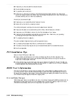
Page 130: ...Problem Solving 5 21...
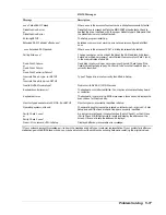
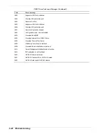
Page 131: ......

Page 132: ......

Page 133: ...rated Parts Breakdown n Exploded View n Field Replaceable Units n Pentium II Processors n Hard Disk Drives n Tape Drives n CD ROM Drive n RAID Controllers and Cache n Network Option Boards n Memory Ex...

Page 134: ...lists for the server s major assemblies Part numbers are also provided for optional hardware Clicking your mouse on an exploded view item number links you to the parts listing Exploded View 4 1 3 13...

Page 135: ...s 233 00015 6 Cable Diskette 2 Connecors 070170 7 Heatsink Pentium II 149952 8 Heatpad Pentium II 149953 9 Heatsink Clip Pentium II 145450 10 Network option Boards Refer to Network Option Boards secti...

Page 136: ...of this chapter Tape Drives Refer to the Tape Drives section of this chapter 25 Power Switch Assy 149976 26 Hard Disk Drives Refer to the Hard Disk Drives section of this chapter 27 Diskette Drive 3...

Page 137: ...ade Kit 203360 333 MHz Pentium II Upgrade Kit 203335 350 MHz Pentium II Upgrade Kit 203337 400 MHz Pentium II Upgrade Kit 203339 Replaceable Parts Description Part Number 266 MHz Pentium II x 512KB 08...

Page 138: ...B EIDE QUANTUM SE 203124 Kit 6 4 GB EIDE QUANTUM SE 203354 Kit 8 4 GB EIDE QUANTUM SE 203356 Kit MOD EXT SCSI Quabbin 203345 01 Replaceable Parts Description Part Number 4 GB UltraWide SCSI HDD ST3452...

Page 139: ...pe 4 8GB Seagate STD28000N 203391 SCSI DAT Autoloader DDS 3 203212 Replaceable Parts Description Part Number SCSI DAT TAPE DDS 3 12 24GB 320548 20 40 GB Internal DLT 4000 320150 4 8 GB STD28000N 32055...

Page 140: ...ache SIMM 4MB Upgrade 203385 Kit AMI MegaRAID LVDS 438 Cache SIMM 16MB Upgrade 203381 Kit AMI MegaRAID LVDS 438 Cache SIMM 32MB Upgrade 203383 Replaceable Parts Description Part Number AMI RAIDExpress...

Page 141: ...Part Number NIC 3COM 3C905 TX 204 00001 NIC Intel PRO 100 030305 Memory Expansion Upgrades Description Part Number 32 MB 1 DIMM ECC 203325 64 MB 1 DIMM ECC 203327 128 MB 1 DIMM ECC 203321 256 MB 1 DIM...

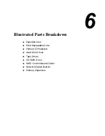
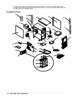
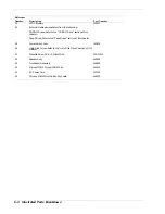
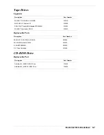
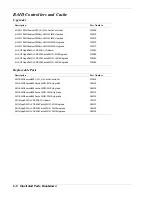
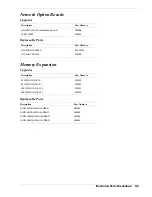
Page 142: ...6 10 Illustrated Parts Breakdown...

Page 143: ...A System Cabling n Before You Begin n Static Precautions n Standard Configuration n RAID Configuration...

Page 144: ...he procedures in this manual make sure that your system is powered off and unplug the AC power cord from the back of the chassis Failure to disconnect power before opening your system can result in pe...

Page 145: ...ry IDE connector to the CD ROM as its master device I and an optional IDE device as its slave device J Another IDE cable O connects the primary IDE connector to the optional first hard drive HD1 as it...

Page 146: ...le C Narrow SCSI to wide SCSI adapter L Secondary IDE connector D Wide SCSI interface cable M IDE master device HD1 E Wide SCSI connector N IDE slave device HD2 F Diskette drive O Primary IDE cable G...

Page 147: ...e the on board SCSI controller to control wide SCSI hard disk drives in the internal bay In this case a SCSI cable C connects the wide SCSI connector to the wide SCSI hard disk drives in internal bay...

Page 148: ...ctor B Optional SCSI tape drive H IDE master device CD ROM C Wide SCSI interface cable I IDE slave device tape D Wide SCSI connector J Secondary IDE cable E Diskette drive K Secondary IDE connector F...

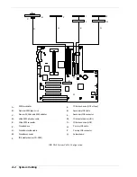
Page 149: ...System Cabling A 7 WIDE SCSI CABLE 68 pins IDE CABLE 40 pins Standard System Cable Routing...

Page 150: ...r Refer to The Installing an Option Board section in the Upgrades and Options chapter to install the controller Once you have installed the controller plug the wide SCSI interface cable into the conne...

Page 151: ...de SCSI interface cable J Secondary IDE cable D Wide SCSI connector K Secondary IDE connector E Diskette drive L System board Controller F Diskette interface cable M Mylex AcceleRAID 250 Controller G...

Page 152: ...B System Setup Utility n System Setup Utility SSU n Creating SSU Diskettes n Running the SSU n Exiting the SSU...

Page 153: ...The SSU works with any compliant configuration CFG or overlay OVL file supplied by the peripheral device manufacturer The I O baseboard includes CFG and OVL files The CFG file describes the characteri...

Page 154: ...properly configured you must use the FLASH resident BIOS Setup Utility F2 to enable it so that you can use the SSU If necessary you can disable the drive after you exit the SSU Information entered usi...

Page 155: ...diskette n From diskette after installing your operating system Insert the SSU diskette in Drive A At the MS DOS prompt type a and press Enter to change to drive A Type SSU and press Enter 3 Follow t...

Page 156: ...tions each task performs For a new mode setting to take effect the user must exit the SSU and restart it n Language this button lets you change the strings in the SSU to strings of the appropriate lan...

Page 157: ...by keeping the task as the center of operation until the user closes the task window There are three ways to launch a task n In the SSU Main window double click on the task name under Available Tasks...

Page 158: ...ick OK 2 When the RCA window appears it displays messages similar to the following Baseboard System Board PCI Card Bus 00 dev 00 Host Processor Bridge PCI Card Bus 00 dev 0D Multifunction Controller P...

Page 159: ...te resource buttons select the desired value and click on Add or Remove 4 After you complete the necessary information click on Save 5 To edit a card click on Load to retrieve the card information Aft...

Page 160: ...System Setup Utility B 9 Adding and Removing ISA Cards Window...

Page 161: ...ected device along with possible choices and the resources associated with those choices displays To make a modification 1 Highlight the function in the Configuration window 2 Double click or press th...

Page 162: ...Configuration 3F8h IRQ4 Serial Port 2 Configuration 2F8h IRQ3 Parallel Port Configuration 378h IRQ7 Parallel Port Mode Extended Capabilities Port DMA 1 FLOPPY DRIVES GROUP Floppy Drive A Option 3 5 1...

Page 163: ...B 12 System Setup Utility System Resource Usage Window...

Page 164: ...n in the Hard Drives list starting at the top of the list 3 To change the priority of an entry in either list select the entry and click on the Move UP or Move Down buttons 4 Click on the Save button...

Page 165: ...and clears the Event Log data The Event Log data file is saved in either text or binary format depending on the output format selected under the Settings menu Selecting Exit returns you to the SSU Ma...

Page 166: ...Emergency Management Port n Emergency Management Port n How the EMP Works n EMP Requirements and Configurations n Setting Up the Server for the EMP n Main EMP Window n Phonebook n Management Plug ins...

Page 167: ...onfiguration The following server operations are available from the Console Manager n Connecting to remote servers n Powering the server ON or OFF n Resetting the server n SEL viewer n SDR viewer n FR...

Page 168: ...communicates with the server allowing the client to remotely reset or power the server up or down The client can also view the server s System Event Log SEL Field Replaceable Unit FRU information or...

Page 169: ...er s COM 2 port is configured for console redirect in BIOS The three EMP access modes are disabled pre boot and always active EMP Access Modes Server Configured for Console Redirect Mode Server is pow...

Page 170: ...port of server and the other into a port on the client machine Modem Configuration On the client the EMP uses the Windows Application Program Interface API to determine if a modem is connected and av...

Page 171: ...access needed The tables above show what is available with a given setting EMP Restricted Mode Access Set Restricted Mode to either enabled or disabled as needed If in enabled mode this means that the...

Page 172: ...ess server control operations and to launch the management plug ins from At the top of the GUI is the menu and tool bar These provide the options to initiate plug ins and other support features A stat...

Page 173: ...nected the status bar says Connected Otherwise the line is blank EMP Console Main Menu n File Exit Exits the EMP n Connect Disconnect disconnects the server connection Re Connect raises the connect di...

Page 174: ...to a server initiating connection generates a warning message It lets you know that the existing connection will be terminated if you continue trying to initiate the new connection You are prompted to...

Page 175: ...p displays dialog level help information Power On Off Selecting Power On Off from the Action menu allows you to power the server on or off with post power up options It generates the Power on off dial...

Page 176: ...n System Reset resets the server with the selected post reset options This operation is not allowed if the server is configured in RESTRICTED mode for EMP operations n Option Group sets the post rese...

Page 177: ...Modify lets you edit an existing entry You select an existing entry from the Server dropdown edit box and modifies the existing phone number before selecting this option Click Save in order to store t...

Page 178: ...w SEL summary info n View all SEL entries n View SEL info by event type n View SEL info by sensor type n Set SEL display mode to either Hex or verbose mode n Set the SEL output file format to either t...

Page 179: ...the SEL By Sensor Type shows all events in the SEL generated by a specific sensor type such as voltage temperature etc By Event displays all the events in the SEL of a particular type for example by m...

Page 180: ...olumn in the SEL Viewer For example if there is a Fan 10 entry in the Sensor Type and Number column of the SEL Viewer by looking at the Sensor type Codes table you can determine that the Baseboard Fan...

Page 181: ...seboard Fan0 BMC Physical Security 26 Chassis Intrusion BMC Secure Mode Violation Attempt 27 EMP password at the time of connecting to the server BMC Secure Mode Violation Attempt 28 Secure Mode Viola...

Page 182: ...Memory EF OC EF E7 02 Memory Parity error Parity Critical Interrupt EF 13 EF E7 00 Bus Timeout Bus timeout Critical Interrupt EF 13 EF E7 02 I O Check I O Channel check NMI Critical Interrupt EF 13 EF...

Page 183: ...server n Settings lets you change operating parameters for the SDR viewer This menu displays the following suboption Display HEX Verbose toggles between HEX mode and interpreted mode of displaying SDR...

Page 184: ...board and product information FRU Info displays the FRU summary information as returned by the server n Settings lets you change operating parameters for the FRU viewer This menu displays the followin...

Page 185: ...yle Front Panel Connector n Fan Interface n Server Management n Hard Drive LED Connector n Chassis Intrusion Connector n VGA Video Port n Keyboard and Mouse n Parallel Port n Serial Ports n RJ 45 Netw...

Page 186: ...ards B DIMM slot 3 M ISA slots for add in boards C DIMM slot 2 N VGA monitor port D DIMM slot 1 O USB connectors E ATX power connector P RJ 45 network connector F Secondary IDE connector Q Serial port...

Page 187: ...e 6 pin mini DIN connector C Printer 25 pin parallel port connector D Serial ports Serial port 9 pin connectors E LAN connector RJ 45 Telephone connector F Green LAN status light When lit LAN is linke...

Page 188: ...ctor locations on the AT style front panel connector A B 1 2 4 8 10 11 12 14 16 19 7 6 C D A Power Switch PWR Pins 1 and 2 B Hard Disk Drive LED DRV Pins 6 and 7 C Speaker SPKR Pins 8 10 and 11 D Powe...

Page 189: ...Black 6 5 VDC Red 16 COM Black 7 COM Black 17 COM Black 8 PWR OK Grey 18 5 VDC White 9 5 VSB Purple 19 5 VDC Red 10 12 VDC Yellow 20 5 VDC Red AT Style Front Panel Connector AT Style Front Panel Conne...

Page 190: ...7 5VSTNDBY 5V standby indication power OK 8 KEYLOCK_SFC_L Keyboard lock signal 9 CPU_NMI Non maskable interrupt indication 10 VCC3 3 3V power supply status input 11 RST_SFC_L System board reset signal...

Page 191: ...ector Pinout Pin Signal Pin Signal 1 Red 9 NC 2 Green 10 GND 3 Blue 11 NC 4 NC 12 DDCDAT 5 GND 13 HSYNC 6 GND 14 VSYNC 7 GND 15 DDCCLK 8 GND Keyboard and Mouse The keyboard and mouse connectors are fu...

Page 192: ...bit 4 15 ERROR_L 7 Data bit 5 16 INIT_L 8 Data bit 6 17 SLCTIN_L 9 Data bit 7 18 25 GND Serial Ports Serial Port Connector Pinout Pin Signal Description 1 DCD Data carrier detected 2 RXD Receive data...

Page 193: ...ir contains the serial input data stream received from the network 4 NC 5 NC 6 RX Receive data minus the negative signal for the RD differential pair contains the same input as pin 3 7 NC 8 NC Diskett...

Page 194: ...ND 5 GND 30 GND 6 SCD2_L 31 GND 7 GND 32 SATN_L 8 SCD3_L 33 GND 9 GND 34 GND 10 SCD4_L 35 GND 11 GND 36 SBSY_L 12 SCD5_L 37 GND 13 GND 38 SACK_L 14 SCD6_L 39 GND 15 GND 40 SRESET_L 16 SCD7_L 41 GND 17...

Page 195: ...R 52 TERMPWR 19 NC 53 NC 20 34 GND 54 GND 35 SCD12_L 55 SATN_L 36 SCD13_L 56 GND 37 SCD14_L 57 SBSY_L 38 SCD15_L 58 SACK_L 39 SCDPH_L 59 RESET_L 40 SCD0_L 60 SMSG_L 41 SCD1_L 61 SSEL_L 42 SCD2_L 62 SC...

Page 196: ...4 DD8 24 GND 5 DD6 25 DIOR_L 6 DD9 26 GND 7 DD5 27 IORDY 8 DD10 28 CSEL 1 K p d 9 DD4 29 IDEDAK_L 10 DD11 30 GND 11 DD3 31 IDEIRQ 12 DD12 32 Reserved N C 13 DD2 33 IDESA1 14 DD13 34 PDIAG_L tied to GN...

Page 197: ...OCHRDY B10 GND C3 LA22 D3 IRQ10 A11 AEN B11 SMEMW_L C4 LA21 D4 IRQ11 A12 SA19 B12 SMEMR_L C5 LA20 D5 IRQ12 A13 SA18 B13 IOW_L C6 LA19 D6 IRQ15 A14 SA17 B14 IOR_L C7 LA18 D7 IRQ14 A15 SA16 B15 DACK3_L...

Page 198: ...45 3 3 V B45 AD14 A15 RST_L B15 GND A46 AD13 B46 GND A16 5 V B16 PCICLK A47 AD11 B47 AD12 A17 GNT_L B17 GND A48 GND B48 AD10 A18 GND B18 REQ_L A49 AD9 B49 GND A19 Reserved B19 5 V A50 KEY B50 KEY A20...

Reviews: