4-20
Upgrading Your System
6.
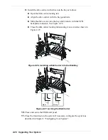
If available, install a DIMM dust cover in any empty DIMM.
7.
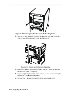
Replace the air duct, left side cover and install and close the front door.
8.
Plug in the server power cord, and power on the server.
Option Boards
This section describes how to install and remove PCI option boards. The system
board includes six PCI bus expansion slots. See Figure 4-19.
Slot1
Slot2
Slot3
Slot4
Slot5
Slot6
Slot1
32 Bit/33 MHz/5V PCI Connector Slot
Slot2
64 Bit/66 MHz/5V PCI Connector Slot
Slot3
64 Bit/66 MHz/5V PCI Connector Slot
Slot4
32 Bit/33 MHz/5V PCI Connector Slot
Slot5
32 Bit/33 MHz/5V PCI Connector Slot
Slot6
32 Bit/33 MHz/5V PCI Connector Slot
Figure 4-19. PCI Slot Locations
Recommended PCI Option Board Locations
Table 4-1. PCI Option Board locations
Option Board
Recommended PCI Slot Location (See Figure 4-20)
1
st
Intel LAN Board
Slot 1
2
nd
Intel LAN Board
Slot 5
3
rd
Intel LAN Card
Slot 6
SecuRAID 110 Controller
Slot 4
Summary of Contents for EXPRESS5800/120Le
Page 1: ... U s e r s G u i d e EXPRESS5800 120Le ...
Page 2: ...xxx ...
Page 3: ... U s e r s G u i d e EXPRESS5800 120Le ...
Page 30: ......
Page 47: ...Setting Up the System 2 17 Figure 2 13 Attaching Cables to the Cable Arm Assembly ...
Page 56: ......
Page 80: ......
Page 140: ...5 22 Problem Solving ...
Page 146: ......
Page 156: ...10 Glossary ...
Page 161: ...xx ...
Page 162: ... 456 01551 N00 ...


