2-8 General Description
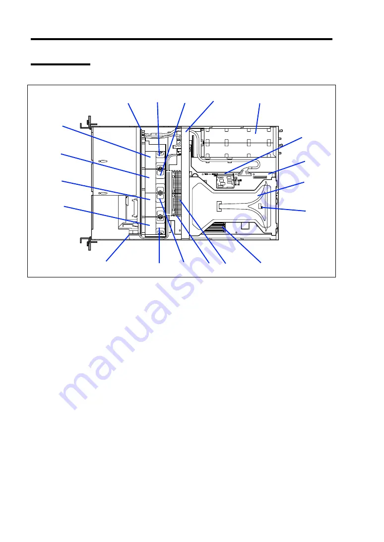
Internal View
1 SCSI backplane
2 Cooling fans
2
-1
: FAN1
2
-2
: FAN2
2
-3
: FAN3
2
-4
: FAN4
3 Support arm
4 Power supply unit
5 Remote management card
6 Mother board
7 Riser card
8 Chassis intrusion switch
9 DIMM (Two DIMMs are mounted as standard in slots #7 and #8.)
10 Processor (mounted under the CPU and heat sink)
11 Processor duct (dashed-line)
12 Front panel board
13 Optional redundant fan slots
13
-1
: FAN5
13
-2
: FAN6
13
-3
: FAN7
13
-4
: FAN8
1
2
-1
2
-2
3
4
6
7
8
9
10
11
2
-3
2
-4
12
13
-1
13
-2
13
-3
13
-4
FRONT
REAR
5
Summary of Contents for Express5800/120Rh-2
Page 142: ...4 46 Configuring Your Server This page is intentionally left blank ...
Page 236: ...7 12 Maintenance This page is intentionally left blank ...
Page 320: ...9 46 Upgrading Your Server Pin Red Pin Red N8103 80F N8103 81F ...
Page 336: ...9 62 Upgrading Your Server This page is intentionally left blank ...
Page 338: ...A 2 Specifications This page is intentionally left blank ...
Page 346: ...C 2 IRQ This page is intentionally left blank ...
Page 406: ...G 4 Product Configuration Record Table This page is intentionally left blank ...


