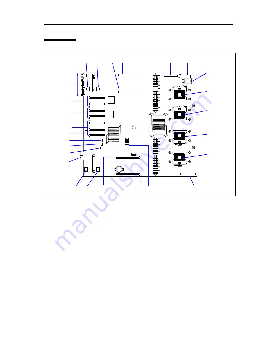
General Description 2-9
Base Board
3
1
-2
11
16
-1
1
-1
2
-B
2
-A
4
5
6
-1
6
-2
16
-2
16
-3
15
6
-3
14
13
12
11
10 2
-D
9
8
6
-4
1
-4
1
-3
7
2
-C
1
Rear fan connector
The last digit represents port number.
2
Memory board connector
The last digit represents port number.
3 Front
panel
connector
4
Power BP interface connector
5 Power
connector
6 Processor
socket
The last digit represents port number.
7
SAS riser connector
8 SATA
connector
9
Internal USB connector
10 Lithium
battery
11
Connectors for external devices
12
I/O riser connector
13
Jumper switch for clearing password
14
Jumper switch for clearing CMOS
15
Internal serial port A
16
PCI Express board slot (PCI #1 to #7 from top)
16-1: PCI #1 and #2 (Hot-plug PCI Express x8)
16-2: PCI #3 and #4 (Non-hot-plug PCI Express x8)
16-3: PCI #5, #6, and #7 (Non-hot-plug PCI Express x4)
Summary of Contents for Express5800/140Rf-4
Page 7: ......
Page 8: ......
Page 9: ......
Page 20: ...x This page is intentionally left blank ...
Page 186: ...4 88 Configuring Your Server 3 Setting menu for VD 0 is displayed ...
Page 194: ...4 96 Configuring Your Server This page is intentionally left blank ...
Page 226: ...5 32 Installing the Operating System with Express Setup This page is intentionally left blank ...
Page 264: ...7 18 Maintenance This page is intentionally left blank ...
Page 413: ...C 4 This page is intentionally left blank ...
Page 457: ...E 22 Installing Windows Server 2003 This page is intentionally left blank ...


