4-28
Upgrading Your System
7.
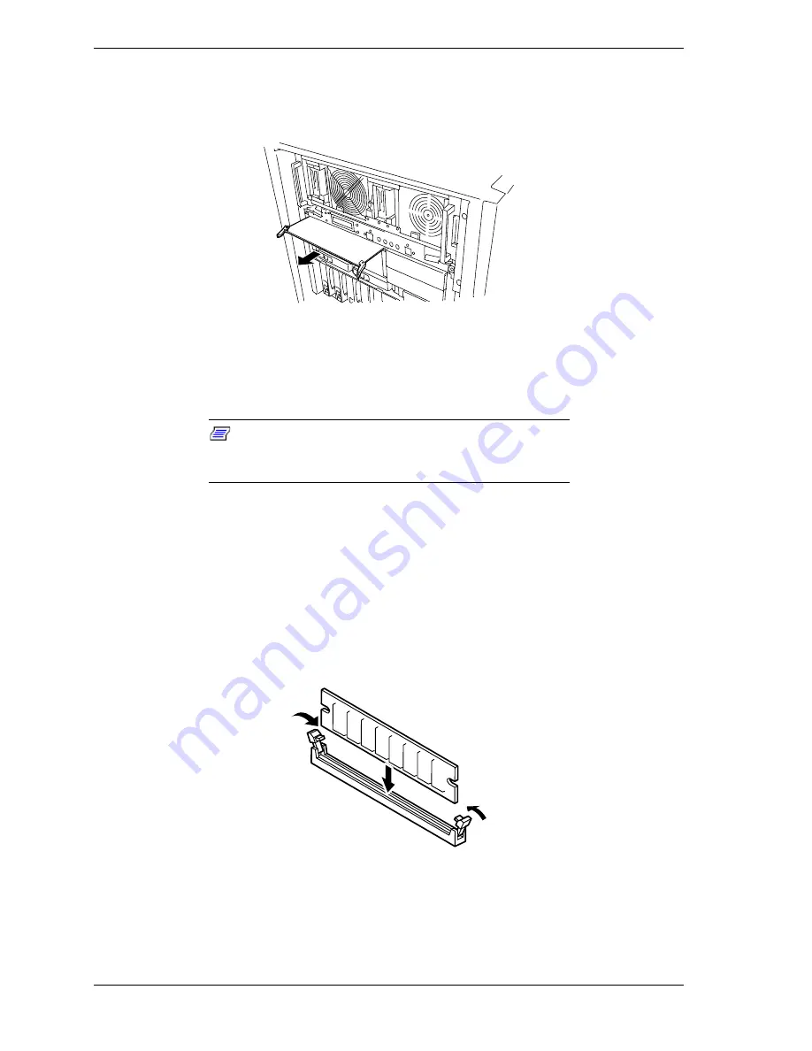
Holding the two fasteners, carefully pull the memory board out until the
edge connectors are free. Place the memory board on an antistatic surface.
See Figure 4-32.
Figure 4-32. Removing the Memory Board
8.
Holding the DIMM module only by the edges, remove it from its antistatic
package.
Note:
When installing DIMMs in empty DIMM
connectors on the memory board, you must remove the
DIMM connector cover first.
9.
DIMMs are keyed so they can only be inserted one way. Position the DIMM
over the socket on the board where you want to install the DIMM. The
notches in the bottom edge of the DIMM mate with the raised bumps in the
DIMM socket.
10.
Press down evenly on the DIMM until it seats correctly. The retaining levers
(see Figure 4-33) on the sockets are not "tools" to aid in the insertion, only
to keep the DIMMs in place and to aid in extraction. The levers will
automatically close in place once the DIMM is fully inserted into the socket.
Figure 4-33. Installing Memory DIMMs
11.
Repeat steps 4 through 6 above to install any remaining DIMMs.
Summary of Contents for Express5800/180Ra-7
Page 1: ... U s e r s G u i d e EXPRESS5800 180Ra 7 ...
Page 2: ...xxx ...
Page 3: ... U s e r s G u i d e EXPRESS5800 180Ra 7 ...
Page 10: ...viii Contents ...
Page 94: ...3 28 Configuring Your System ...
Page 134: ...4 40 Upgrading Your System A B C Figure 4 43 Recabling the SCSI Interface Cable ...
Page 166: ...4 72 Upgrading Your System ...
Page 206: ...5 40 Problem Solving ...
Page 207: ...A Specifications Basic System Unit BSU Disk Expansion Unit DEU ...
Page 212: ...A 6 Specifications ...
Page 218: ...B 6 Interrupt Request PCI IRQ Device I O Port Address Assignments ...
Page 229: ...D ROMPilot BIOS Error Codes ROMPilot BIOS Error Codes ...
Page 232: ...D 4 ROMPilot BIOS Error Codes ...
Page 242: ...10 Glossary ...
Page 246: ...4 Equipment Log ...
Page 250: ...Index 4 ...
Page 251: ...xx ...
Page 252: ... 456 01516 000 ...


