Upgrading Your System 4-63
3.
Unlock (if locked) the mechanical lock at the top of the front door of your
system tower cabinet and open the door.
4.
Power off the system. Ensure the power cords are unplugged from the AC
wall outlet.
5.
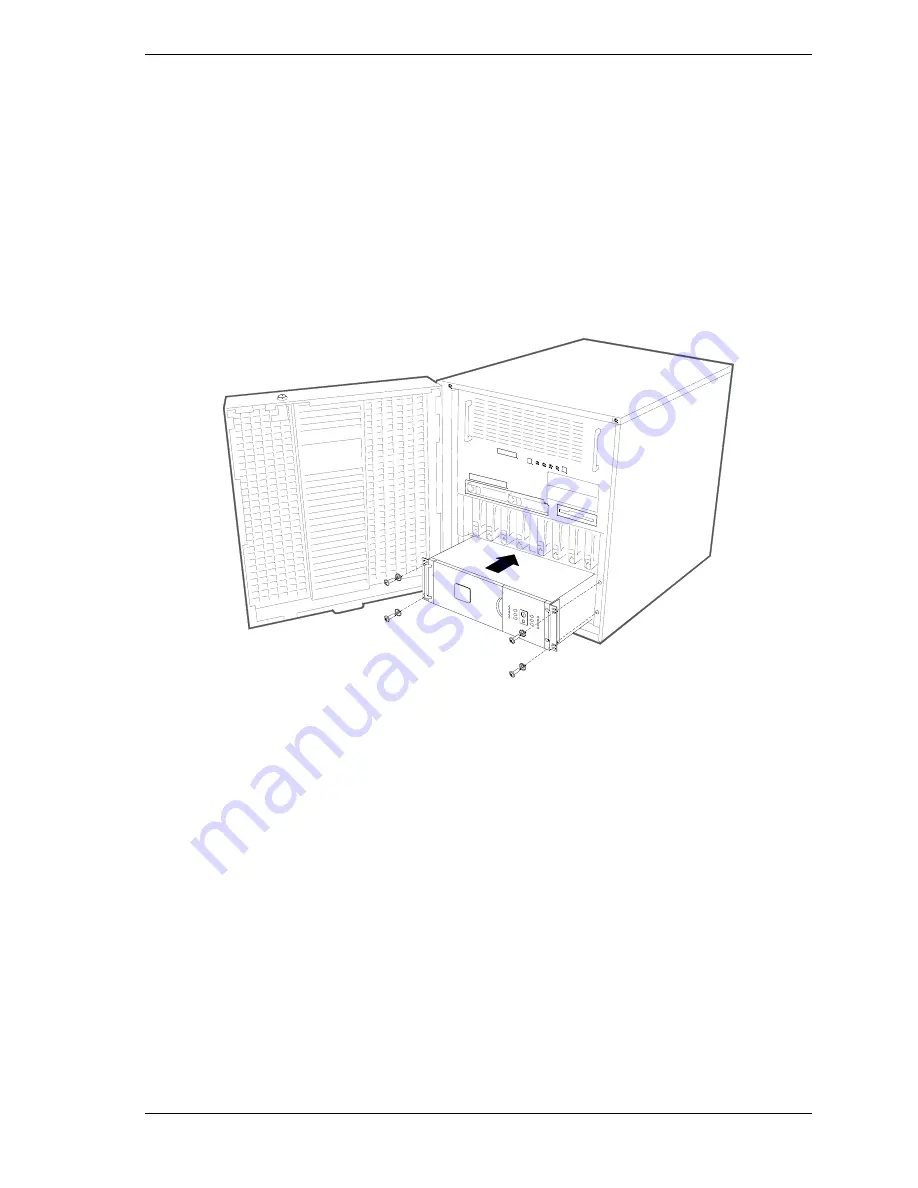
Remove the four screws securing the blank panel to the mounting rails at the
bottom of the tower cabinet and remove the blank panel.
6.
With the aid of another person, slide the UPS into the bottom of the tower
cabinet and secure the UPS to the vertical mounting rails inside the tower
with four M5 screws (see Figure 4-69).
Figure 4-69 Installing the UPS
7.
Connect the UPS power cable to the AC source. Refer to the documentation
provided with your UPS.
8.
Switch on the UPS to execute a self-test before connecting any system
components. See the Installation and Operation section of the
“Uninterruptible Power Source User’s Manual”.
9.
Check the Site Wiring Fault indicator (see Figure 4-70, A)
If the indicator is illuminated, have a qualified electrician correct the
building wiring. Faults can be caused by a missing ground, a hot and
neutral polarity reversal, or an overloaded neutral circuit.
Summary of Contents for Express5800/180Ra-7
Page 1: ... U s e r s G u i d e EXPRESS5800 180Ra 7 ...
Page 2: ...xxx ...
Page 3: ... U s e r s G u i d e EXPRESS5800 180Ra 7 ...
Page 10: ...viii Contents ...
Page 94: ...3 28 Configuring Your System ...
Page 134: ...4 40 Upgrading Your System A B C Figure 4 43 Recabling the SCSI Interface Cable ...
Page 166: ...4 72 Upgrading Your System ...
Page 206: ...5 40 Problem Solving ...
Page 207: ...A Specifications Basic System Unit BSU Disk Expansion Unit DEU ...
Page 212: ...A 6 Specifications ...
Page 218: ...B 6 Interrupt Request PCI IRQ Device I O Port Address Assignments ...
Page 229: ...D ROMPilot BIOS Error Codes ROMPilot BIOS Error Codes ...
Page 232: ...D 4 ROMPilot BIOS Error Codes ...
Page 242: ...10 Glossary ...
Page 246: ...4 Equipment Log ...
Page 250: ...Index 4 ...
Page 251: ...xx ...
Page 252: ... 456 01516 000 ...


