Upgrading Your System 4-9
Determining Drive Status
Status LEDs arranged in sets of three below each of the two hot-swapping bays
monitor the status of each drive. When a yellow LED is on continuously, it is
okay to hot-swap (remove and replace) a bad drive with a good one. You DO
NOT need to shut down the server to hot-swap a drive. Table 4-1 provides a
description of SCSI drive status LEDs.
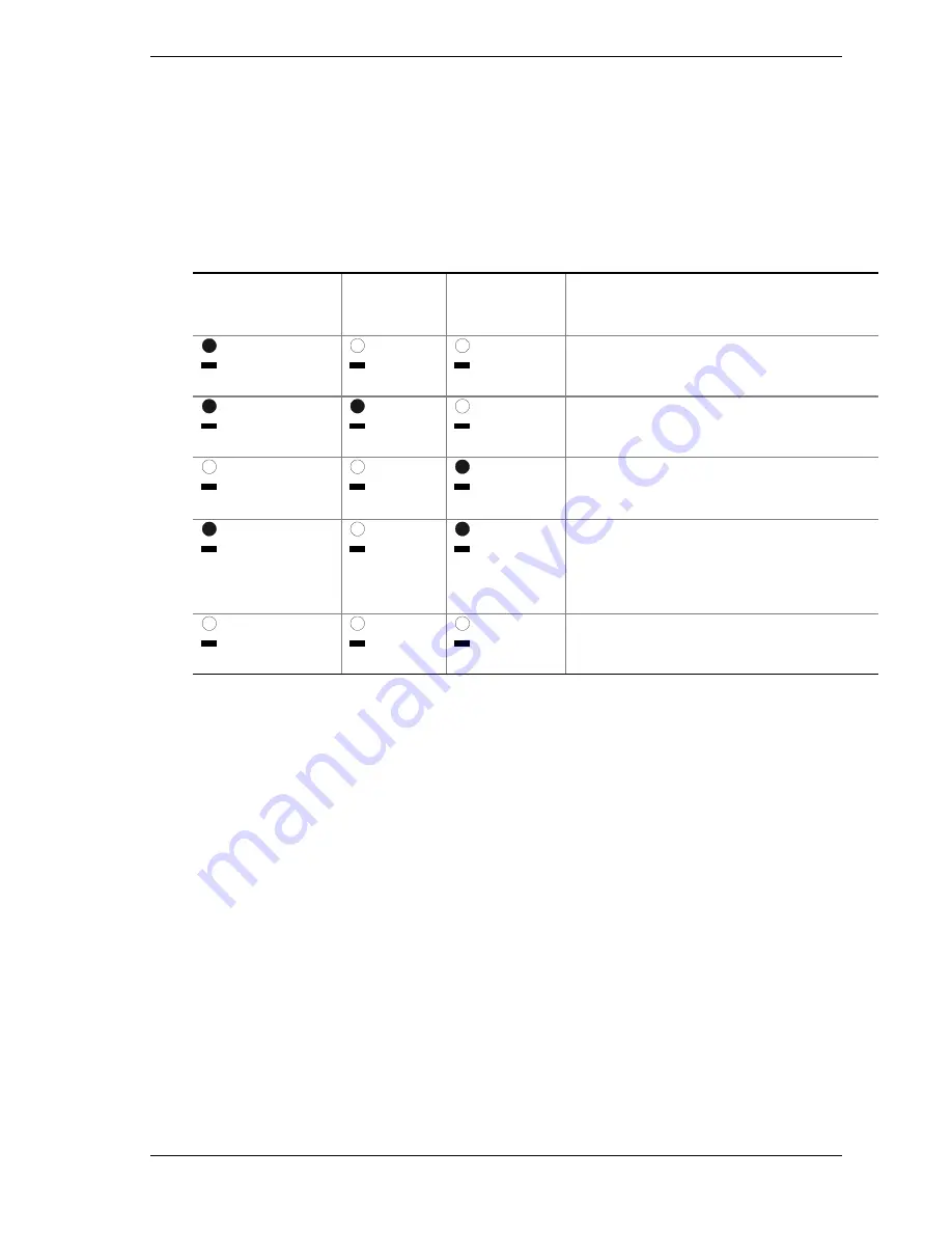
Table 4-1. SCSI Drive Status LED Descriptions
SCSI drive present,
power on
Green LED, A
SCSI drive
active
green LED, B
SCSI drive
faulty*
yellow LED, C
Description and action if needed
On
Off
Off
Drive is present with power.
On
Blinking
Off
Drive is present with power and is being
accessed.
Off
Off
On
Drive CAN be replaced. Steady yellow fault
light indicates drive has a problem. Power to
drive is off.
On
Off
Slow blinking
Drive SHOULD NOT be replaced at this time.
A slowly blinking yellow fault light indicates that
a drive that has just been replaced is in
recovery mode (drive array being rebuilt).
Power to drive is on.
Off
Off
Off
There is no drive installed in the bay.
*
The hot-swap controller is responsible for turning the yellow drive fault LED on or off according to the states
specified by commands received via SAF-TE and IMB.
1.
Look at the yellow LEDs below the hot-swapping bays to determine which
drive is bad.
2.
Push on the drive carrier latch of the bad drive, and while grasping the
handle, pull the assembly toward you to disengage the drive from the
backplane connector.
3.
Before moving the drive any further, wait 30 seconds. This elapsed time
allows the drive platter to stop rotating.
4.
Carefully slide the assembly out of the bay, and place it on an antistatic
surface.
5.
Orient the new carrier and drive assembly in front of the hot-swapping bay
guide rails so that the metal fingers of the perforated metal bracket attached
to the carrier are facing up. Make sure you correctly place the carrier into
the guide rails to avoid damage.
6.
While grasping only the drive carrier handle, firmly push the assembly into
the bay until the driver carrier latches.
Summary of Contents for Express5800/180Rb-7
Page 1: ... U s e r s G u i d e EXPRESS5800 180Rb 7 ...
Page 2: ...xxx ...
Page 3: ... U s e r s G u i d e EXPRESS5800 180Rb 7 ...
Page 10: ...viii Contents ...
Page 58: ...2 24 Setting Up the System ...
Page 146: ...4 40 Upgrading Your System ...
Page 166: ...5 20 Problem Solving ...
Page 186: ...10 Glossary ...
Page 190: ...4 Equipment Log ...
Page 195: ...xx ...
Page 196: ... 456 01564 001 ...


