background image

2-4


Setting Up the System

Rack-Mount Subsystem Assembly

This section provides the instructions for assembling the rack-mount server into
a standard EIA 19-inch rack cabinet.

Unpacking the Rack Mounting Hardware

Although the rack mounting hardware is inspected and carefully packaged at the
factory, damage may occur during shipping. Follow these steps for unpacking.

1. 

Visually inspect the shipping containers; notify your carrier immediately of
any damage.

2. 

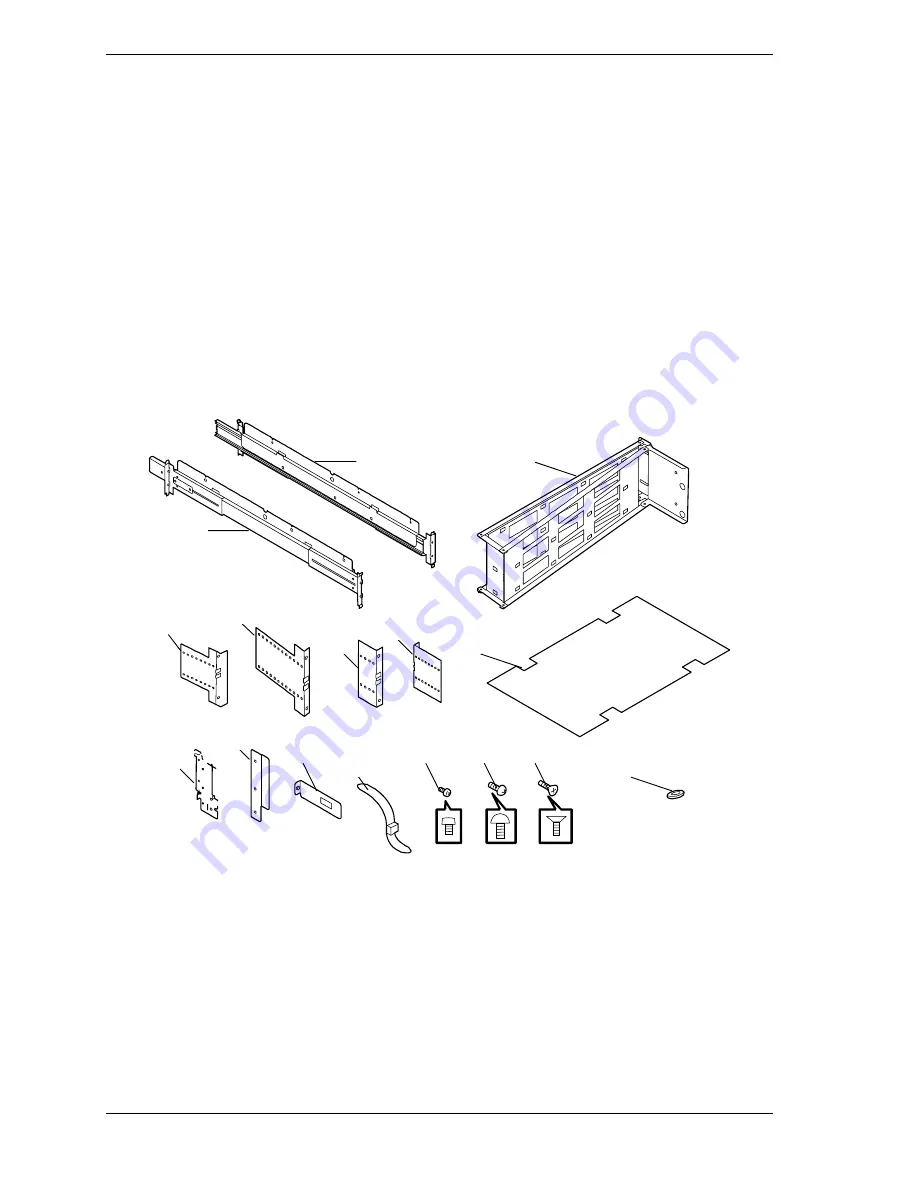
Carefully remove the rack mounting hardware and verify the parts.  See
Figure 2-1 and Table 2-1. If parts are missing or the hardware is damaged,
notify your server representative.

A

C

D

E

F

G

H

I

J

K

L

M

N

O

P

B

Figure 2-1.  Rack Mounting Hardware

Summary of Contents for Express5800/180Rb-7

Page 1: ... U s e r s G u i d e EXPRESS5800 180Rb 7 ...

Page 2: ...xxx ...

Page 3: ... U s e r s G u i d e EXPRESS5800 180Rb 7 ...

Page 4: ...ator control Since implementation by customers of each product may vary the suitability of specific product configurations and applications must be determined by the customer and is not warranted by NEC Computers Inc To allow for design and specification improvements the information in this document is subject to change at any time without notice Reproduction of this document or portions thereof w...

Page 5: ...ooling 1 8 Boardset Description 1 9 Boardset Features 1 10 Processor Overview 1 12 Memory Overview 1 12 DIMM Installation Sequence 1 13 Peripheral Ports 1 14 Super I O Chip 1 14 Serial Ports 1 14 Parallel Port 1 14 Add in Board Slots 1 14 Video 1 14 SCSI Controller 1 15 IDE Controller 1 15 Keyboard and Mouse 1 16 Remote Power On Wake On LAN Function 1 16 System Security 1 16 Security with Mechanic...

Page 6: ...ys 3 3 Using the BIOS Setup Utility 3 3 Using the BIOS Setup Utility 3 3 BIOS Setup Configuration Settings 3 4 Main Menu 3 5 Primary Master Slave Submenu 3 6 Processor Information Submenu 3 7 Keyboard Features Submenu 3 7 Advanced Menu 3 8 PCI Configuration Submenu 3 9 I O Device Configuration Submenu 3 10 Advanced Chipset Control Submenu 3 11 Security Menu 3 12 Server Menu 3 13 System Management ...

Page 7: ...ng 3 37 Upgrading BIOS 3 37 Preparing for the Upgrade 3 37 Recording the Current BIOS Settings 3 37 Obtaining the Upgrade Utility 3 37 Creating a Bootable Diskette 3 38 Creating the BIOS Upgrade Diskette 3 38 Upgrading BIOS 3 39 Recovering BIOS 3 39 Changing BIOS Language 3 40 Using the Firmware Update Utility 3 40 Running the Firmware Update Utility 3 40 Installing Video Drivers 3 41 Using the Sy...

Page 8: ...Removing a Processor 4 26 Installing a Processor 4 28 Front Side Bus FSB Termination Board Assembly 4 29 Removing a Termination Board 4 29 Installing a Termination Board 4 29 Optional Five to Eight CPU Upgrade Kit 4 31 5 Problem Solving Problem Solving 5 2 Static Precautions 5 2 Resetting the System 5 2 Troubleshooting Checklists 5 3 Initial System Startup 5 3 Running New Application Software 5 4 ...

Page 9: ...r Messages 5 13 POST Error Codes and Messages 5 13 How to Identify BIOS 5 19 BIOS Revision Level Identification 5 19 A System I O Addresses Memory Map PCI Configuration and Device Map Interrupts Video Mode Assignments System I O Addresses A 2 Memory Map A 3 PCI Configuration and Device Map A 4 Interrupts A 5 Video Modes A 7 Glossary Equipment Log Index ...

Page 10: ...viii Contents ...

Page 11: ...lity and the Symbios Configuration Utility which is used to configure SCSI devices in your system This chapter also provides information on system board switch settings Chapter 4 Upgrades and Options provides you with instructions for upgrading your system with additional processors optional memory options cards peripheral devices and redundant power supply Chapter 5 Problem Solving contains helpf...

Page 12: ...ss of life CAUTION Cautions indicate situations that can damage the system hardware or software Note Notes give important information about the material being described Names of keyboard keys are printed as they appear on the keyboard For example Ctrl Alt or Enter Text or keystrokes that you enter appear as boldface type For example type abc123 and press ENTER File names are printed in uppercase l...

Page 13: ...de at the time it was developed and released Getting Started Sheet The Getting Started Sheet provides several easy to follow steps to become familiar with your server documentation and to complete your installation successfully Network Operating System Configuration Guide This guide contains supplemental instructions needed to install and configure your server Windows 2000 Windows NT 4 0 and Novel...

Page 14: ...system is powered off and unplug the AC power cords from the back of the chassis Failure to disconnect power before opening your system can result in personal injury and equipment damage In the U S A and Canada the power cord must be a UL listed detachable power cord in Canada CSA certified type ST or SJT 14 AWG 3 conductor This cord is provided with a molded on NEMA type 5 15P plug cap at one end...

Page 15: ... the external ports Remote Earths To prevent electrical shock connect all local individual office computers and computer support equipment to the same electrical circuit of the building wiring If you are unsure check the building wiring to avoid remote earth conditions Earth Bonding For safe operation only connect the equipment to a building supply that is in accordance with current wiring regulat...

Page 16: ...system warm or cool to room temperature before using it Keep the system away from magnetic forces Keep the system dry Do not wash the system with a wet cloth or pour fluid into it Protect the system from being bumped or dropped Check the system for condensation If condensation exists allow it to evaporate before powering on the system Keep the system away from dust sand and dirt ...

Page 17: ...atures Peripherals Hot swap Power Supplies System Cooling Boardset Description Boardset Features Processor Overview Memory Overview DIMM Installation Sequence Peripheral Ports Add in Board Slots Video SCSI Controller IDE Controller Keyboard and Mouse Remote Power On Wake On LAN Function System Security Reconfiguration ...

Page 18: ...rs An additional processor mezzanine carrier with cache coherency filters An additional memory module and additional memory Add in I O boards Table 1 1 lists the server physical specifications Table 1 1 Server Physical Specifications Specification Value Height 31 12 cm 12 25 inches 7u Width 44 45 cm 17 5 inches Depth 71 12 cm 28 0 inches Weight 51 4 kg 113 lbs minimum configuration 60 kg 132 lbs m...

Page 19: ...e 3 5 inch hot swapping bays These bays allow hot swapping of hard disk drives without shutting down the server Ten hot plug PCI I O expansion slots The plastic front bezel provides airflow and easy access to drives in the hot swapping bays The removable top covers provide proper airflow and easy access to components inside the server Only technically qualified personnel should remove the server c...

Page 20: ...ew Chassis Front Controls and Indicators Figure 1 2 shows the chassis front controls and indicators Table 1 3 provides a description of the chassis front controls and indicators Figure 1 2 Front Controls and Indicators ...

Page 21: ... continuously it indicates an asserted fault status on one or more hard disk drives in the hot swapping bay When flashing it indicates drive reset in progress H Front panel LCD Displays information about processor type and failure codes Status LEDs for SCSI Drives in Hot swapping Bays I Drive power LED green When lit continuously it indicates the presence of the drive and power on the drive J Driv...

Page 22: ...rchassis Management Bus ICMB connectors port 1 and 2 J PCI LAN controller board for 100Base TX 10Base TX Fast Ethernet networks with RJ 45 Ethernet connector and status lamps Top lamp ACT LNK Blinking Green linked to network sending or receiving data OFF not linked to network Bottom lamp 100TX ON Orange 100 Mbps network connection OFF 10 Mbps network mconnection K Power supplies in this view suppl...

Page 23: ...n integral heatsink is required The drives are mounted in the carrier with four fasteners and the carrier snaps into the chassis with a locking handle A single metal EMI shield and plastic door cover the drive bays A hot swapping bay is provided for drives that are 3 5 inches wide and 1 0 or 1 6 inches high Drives can consume up to 24 watts of power and must be specified to run at a maximum ambien...

Page 24: ... max total combined output of 3 3 V and 5 5 V not to exceed 195 W 12 V at 36 0 A with 42 0 A 10ms peak 24 V at 100 mA 12 V at 1 0 A 5 V standby 1 0 A Each supply docks to a 36 pin connector on the system midplane System Cooling The server contains two independent cooling subsystems The upper system cooling the front panel profusion carrier and I O carrier 5 1 redundancy The lower system cooling th...

Page 25: ...FSB terminator modules Cache coherency filters PCI hot plug PHP I O carrier Low voltage differential SCSI LVDS hot swap disk backplane I O riser board Two memory modules Front panel controller board Midplane The profusion carrier is mounted horizontally toward the front of the chassis and the PHP I O carrier is mounted horizontally towards the rear of the chassis The carriers plug into connectors ...

Page 26: ...n processors Pentium III Xeon processor packaged in an S E C cartridge Installed Up to eight Pentium III Xeon processors packaged in single edge contact S E C cartridges and installed in 330 pin Slot 2 processor connectors operating at 1 8 V to 3 5 V The profusion carrier provides connectors for two processor mezzanine boards Each mezzanine board provides four Slot 2 connectors The carrier s volta...

Page 27: ...ive Electronics IDE interface supports one IDE bus PS 2 compatible keyboard mouse controller Two universal serial bus USB ports I O riser board This board contains all legacy I O connections it plugs into an edge connector on the PHP I O carrier PS 2 compatible keyboard and mouse ports interchangeable PS 2 compatible parallel port Analog VGA 15 pin video port Two PS 2 compatible 9 pin serial ports...

Page 28: ...sors The processor external interface is multiprocessor MP ready and operates at 100 MHz The processor contains a local APIC unit for interrupt handling in MP and uniprocessor UP environments The L2 cache is located on the same die as the processor core and L1 cache The cache Is offered in 1 MB and 2 MB configurations Is ECC protected Operates at the full core clock rate Memory Overview Main memor...

Page 29: ... at a time DIMM Installation Sequence A single carrier will support DIMM population in various configurations empty sockets included However when fewer than 16 DIMMs are installed on a memory module the preferred population order is to start from the lowest J number and populate sequentially to the highest This recommendation helps maintain optimal signal integrity and thermal performance Note Max...

Page 30: ...Super I O registers enables the parallel port and determines the port address and interrupt When disabled the interrupt is available to add in boards Add in Board Slots The I O carrier has ten 64 bit PCI buses nine available contained in four PCI segments PCI slot 10 contains the system LAN controller board PCI A provides for PCI slots 1 and 2 33 MHz dual channel LVDS SCSI controller video and PII...

Page 31: ...fers on PCI up to the maximum rate of 132 MB sec using on chip buffers In the hot swap SCSI hard drive bay the system supports up to two 1 inch SCSI hard disk drives The 5 25 inch removable media bay supports one SCSI or IDE device the controller itself supports more devices but the 5 25 inch bay can contain a maximum of one device SCSI devices do not need to operate at the ultra transfer rate All...

Page 32: ...wer On Wake On LAN Function The remote power on Wake On LAN function turns on the system power by way of the network If the system power is set to Off it can be turned on remotely by sending a specific packet from the main computer to the remote system System Security To help prevent unauthorized entry or use of the system the system includes a full lockable front cover and internal software locks...

Page 33: ...t use the keyboard or the mouse until you enter the user password You can use Setup to put the server in secure boot mode If BIOS detects a disk in the CD ROM drive or a diskette in floppy drive A at boot time it prompts you for a password When you enter the password the server boots from the disk in the CD ROM drive or the diskette in drive A Entering a password also disables secure mode If there...

Page 34: ...the server is in secure mode To exit secure mode enter your user password Reconfiguration If a CPU or a memory DIMM board error was detected during execution of POST Power On Self Test after system power is turned on the reconfiguration function isolates the failed CPU or memory DIMM board and continues operation You should replace the failed device as soon as possible This function is enabled onl...

Page 35: ...2 Setting Up the System Overview Selecting a Site Unpacking the System Rack Mount Subsystem Assembly Getting Familiar with the System Making Connections Connecting the Power Cord Using the System ...

Page 36: ...ets applicable for the electrical code of the region WARNING Be sure the power service connection is through a properly grounded outlet Clean dust free and well ventilated Front and rear ventilating openings kept free of obstructions Away from sources of heat vibration or physical shock Isolated from strong electromagnetic fields and electrical noise produced by electrical devices such as air cond...

Page 37: ...let The minimum server configuration weighs 51 kg 113 lbs the maximum weighs 63 5 kg 140 lbs Use only a hand truck or other mechanical assist unit to move the server from one location to another When you receive your system if the shipping boxes are damaged note the damage and if possible photograph it for reference After removing the contents of the containers keep the cartons and the packing mat...

Page 38: ...s inspected and carefully packaged at the factory damage may occur during shipping Follow these steps for unpacking 1 Visually inspect the shipping containers notify your carrier immediately of any damage 2 Carefully remove the rack mounting hardware and verify the parts See Figure 2 1 and Table 2 1 If parts are missing or the hardware is damaged notify your server representative A C D E F G H I J...

Page 39: ...Be sure that power to the system is turned off and unplugged All voltage is removed only when the power cords are unplugged Avoid excessive vibration and shock Dropping an electronic component can cause serious damage Do not disconnect or remove parts other than those specified in the procedure Do not touch I O connector pins All screws are Phillips head unless otherwise specified On completion of...

Page 40: ...able support to prevent it from falling over when one or more servers are extended in front of it on slide assemblies The anchors must be able to withstand a force of up to 113 kg 250 lbs You must also consider the weight of any other device installed in the rack MAIN AC POWER DISCONNECT You are responsible for installing an AC power disconnect for the entire rack unit This main disconnect must be...

Page 41: ...n of the mounting screws in the system rack where the server is to be installed see Figure 2 2 The template can be placed on the front and rear of the rack cabinet to show the mounting screw hole positions of the server guide rail assemblies front faceplate screws and cable retention arm plate Note Ensure that the template is aligned properly so that the mounting screw hole cut outs are at the sam...

Page 42: ...unted for the Rack Mounting Rail Assemblies front bezel thumbscrews holes and Cable Retention Arm Plate See Figure 2 3 for the front vertical mounting rail and Figure 2 4 for the rear vertical mounting rails Note For vertical reference every three screw holes on the rack vertical mounting rail are equal to 1U 1 75 inches Mounting holes in the vertical rails of equipment racks are commonly spaced i...

Page 43: ...the front vertical mounting rails for the cage nuts which hold the screws of the server faceplate see Figure 2 3 and the Cable Retention Arm see Figure 2 4 4 Insert four M5 cage nuts in their marked locations on the front vertical mounting rails see Figure 2 5 as follows Position the cage nut on the inside of the front vertical mounting rails Hook the side lip of a cage nut into the square hole in...

Page 44: ... the rack cabinet allowing cables to swing in and out of the way as the server slides back and forth within the rack cabinet see Figure 2 6 All the server cables can be tie wrapped to the cable retention arm Note For easy installation of the cable retention arm install the cable retention arm on the rear of the server before mounting the server into the rack cabinet Figure 2 6 Cable Retention Arm ...

Page 45: ...otrude out on the inside edge of the chassis facing the power supplies A Figure 2 7 Attaching Arm Bracket 1 to the Rear of Server 3 Using three 6 32 screws secure arm bracket 2 see Figure 2 8 A to the outside edge of arm bracket 1 just installed on the rear of the server The rear edge of the metal cabinet should now be sandwiched in between Arm Bracket 1 A and Arm Bracket 2 B providing extra struc...

Page 46: ...2 10 A by placing it over the top screw post that protrudes out on the inside edge of the chassis facing the power supplies and secure with a 6 32 screw A Figure 2 10 Attaching Arm Bracket 3 5 Using two screws attach one end of the cable retention arm to arm bracket 1 installed on the rear of the server see Figure 2 11 ...

Page 47: ...step 1 7 Using two M5 screws attach one of the arm plates to the cage nuts in the left rear vertical mounting rail of your rack cabinet see Figure 2 12 There are four arm plates A B C and D available to fit the different types of rack cabinets see Figure 2 1 and Table 2 1 Figure 2 12 Attaching the Arm Plate to the Rack Cabinet ...

Page 48: ...see Figure 2 13 located on the right side of the rack cabinet The tabs on the front and rear of the slide rail assembly help to align it with the holes previously marked in the vertical mounting rail 3 Install two M5 screws and two washers that secure the front of the slide rail assembly to the front vertical mounting rail and tighten loosely See Figure 2 13 A B C D A Screw and washer B Vertical r...

Page 49: ... only a mechanical assist unit to lift it off the shipping pallet The minimum server configuration weighs 51 kg 113 lbs the maximum weighs 63 5 kg 140 lbs Use only a hand truck or other mechanical assist unit to move the server from one location to another 1 Pull the two extension rails see Figure 2 14 A out of each rack mounting assembly on the rack cabinet until they lock in place 2 Use a mechan...

Page 50: ...ides will move easier 5 Check that the server slides in and out of the rack cabinet Grasp the two handles on the front of the server and slowly pull the server out and push it back in A Figure 2 15 Sliding the Server into the Rack 6 Using two 6 32 screws attach the other end of the cable retention arm to the metal mounting bracket installed on the left rear vertical mounting rail see Figure 2 16 F...

Page 51: ...and forth a few times to ensure proper movement of the arm see Figure 2 17 Figure 2 17 Swinging the Cable Retention Arm 8 Bundle all the server cables together and tie wrap them to the cable retention arm see Figure 2 18 Figure 2 18 Attaching the Cable Retention Arm ...

Page 52: ...d to configure the system You may remove them after running the BIOS Setup Utility For information on running the BIOS Setup Utility refer to Chapter 3 Configuring Your System of this User s Guide Connect your keyboard monitor and mouse See Figure 1 3 in Chapter 1 of this User s Guide Connect any external peripheral devices such as a printer or modem by following the instructions included with the...

Page 53: ...nated in a grounding type male plug designed for use in your region It must have certification marks showing certification by an agency acceptable in your region The power cord must be less than 2 7 meters 9 0 feet long After the power cord is plugged in confirm that the power status lamp on the power unit flashes If the lamp is off a failure occurred in the power unit see Table 1 3 System Status ...

Page 54: ...isk while the access lamp is lit may damage data being stored on the floppy disk After turning off the server wait at least 40 seconds before turning it on again Cycling the power immediately may cause malfunction or failures of the server Before relocating the server turn off the power and unplug the power cord from the outlet Moving the server when it is powered may cause malfunction or failures...

Page 55: ...power control unit is powered on 3 Press the push button power on off switch on the front panel see Figure 2 20 Verify that the server power on LED is lit Note The server management logic on your system board monitors and logs system voltage changes When powering up or down your system you may experience a 1 5 second delay from the time you press the push button power on off switch on the front pa...

Page 56: ...e display unit Note For error messages that appear on the display unit refer to subsection POST Error Codes and Messages in Chapter 5 of this Guide CAUTION Always allow POST to complete before powering down your system If you have problems powering on your system refer to Problem Solving in Chapter 5 of this User s Guide After you have successfully powered on your system insert the EXPRESSBUILDER ...

Page 57: ...power off procedures Forcing a Power Shutdown A forced power shutdown can be used when the power on off switch does not power off the server or the reset functions do not work To perform a forced power shutdown Press in on the power on off switch located on the front panel of the server for at least 4 seconds to force the server power off To power on after a forced shutdown wait 10 seconds and the...

Page 58: ...2 24 Setting Up the System ...

Page 59: ...Using the BIOS Setup Utility Using the System Setup Utility SSU FRU and SDR Load Utility Upgrading BIOS Using the Firmware Update Utility Installing Video Drivers Using the Symbios SCSI Utility Configuring the RAID Controller Setting the Configuration Switches ...

Page 60: ...U can be run from either the configuration software CD ROM or from a set DOS bootable diskettes Information entered via the SSU overrides information entered via Setup 3 18 FRUSDR Load Utility Use to update the Field Replacement Unit FRU Sensor Data Record SDR and Desktop Management Interface DMI flash components 3 32 BIOS Update Utility Use to update BIOS or recover from a corrupted BIOS update 3...

Page 61: ...ire a diskette or an operating system present to run However parmeters set with the BIOS Setup Utilitythat can also be set with the SSU will be overwritten by the SSU the next time the SSU is run Using the BIOS Setup Utility You access the BIOS Setup utility when you turn on or reboot your system To run the BIOS Setup Utility perform the following procedure 1 Power on or reboot the system Press F2...

Page 62: ...e current menu item to the next value Enter Activate submenus select feature options and change feature values F9 Display the following message Setup Confirmation Load default configuration now Yes No The Yes button will be highlighted If you press Enter all Setup fields return to their default values If you press ESC or select No the server returns to the configuration it had before you pressed F...

Page 63: ...ia format To support the 1 25 MB 3 5 inch option requires a 3 5 inch 3 mode diskette drive Legacy Diskette B Disabled 360 KB 5 1 2 MB 5 720 KB 5 1 44 1 25 MB 3 2 88 MB 3 Select the diskette type for drive B The size 1 25 MB 3 5 inch option refers to a 1024 byte sector Japanese media format To support the 1 25 MB 3 5 inch option requires a 3 5 inch 3 mode diskette drive Primary Master CD ROM Select...

Page 64: ...able device is installed here Multisector Transfers Disabled 2 4 8 or 16 sectors Displays status of multisector transfers Autotyped by BIOS LBA Mode Control Disabled Enabled Displays status of Logical Block Access Autotyped by BIOS 32 bit I O Disabled Enabled Enabled allows 32 bit IDE data transfers Transfer Mode Standard Fast PIO 1 2 3 or 4 FPIO 3 DMA 1 FPIO 4 DMA 2 Selects the method of transfer...

Page 65: ... processor 4 L2 cache size Right Processor 1 CPU ID Displays board 2 processor 1 stepping ID Right Processor 1 Cache Size Displays board 2 processor 1 L2 cache size Right Processor 2 CPU ID Displays board 2 processor 2 stepping ID Right Processor 2 Cache Size Displays board 2 processor 2 L2 cache size Right Processor 3 CPU ID Displays board 2 processor 3 stepping ID Right Processor 3 Cache Size Di...

Page 66: ... LBA However some operating systems may use the cylinder head sector CHS See your OS documentation for further help Pause Before Boot Disabled Enabled Enables five second pause before booting the OS Hot Plug PCI Master Control Disabled Enabled Enabled allows the creation of the hot plug resource table Hot Plug PCI Allocation Level Displayed Minimum Maximum Sets the amount of resources to allocate ...

Page 67: ...66 MHz PCI Bus speed PCI Device Embedded SCSI A Selects PCI Mode submenu for embedded LVDS controller PCI Devices Selects PCI Mode submenu for PCI slots PCI Mode Submenu Feature Option Description Option ROM Scan Enabled Disabled Enables option ROM scan Enable Master Enabled Disabled Enables device s as a PCI bus master Latency Timer Default 0020h 0040h 0060h 0080h 00A0h 00C0h 00E0h Specifies the ...

Page 68: ...ess for serial port B Interrupt IRQ3 IRQ4 Sets the interrupt for serial port B Parallel Port Disabled Enabled Auto OS Controlled Configure the parallel port using these options Disabled no configuration Enabled user configuration Auto BIOS or OS chooses the configuration OS Controlled displayed when controlled by the OS Mode Output only Bidirectional EPP ECP Set the mode for the parallel port Base...

Page 69: ...sized and enabled Disabled causes the L2 cache to be disabled for core clock frequency bus ratios equal to 2 Multiboot Support Disabled Enabled Only enable this option when the total number of bootable devices is fewer than eight Override PHP Switches Disabled Enabled If enabled all hot plug PCI slots will power up If disabled only those slots whose PCI hot plug retention mechanism is engaged will...

Page 70: ...ess User Administrator Controls access to diskette drives Secure Mode Timer Disabled 1 min 2 min 5 min 10 min 20 min 1 hr 2 hr Select the time out period of keyboard or mouse inactivity required before the secure mode activates A password must be entered for the secure mode to work Secure Mode Hot Key Ctrl Alt Disabled A B Z Select a hot key and then press Ctrl Alt your hot key to place the system...

Page 71: ... from the FPC firmware Modem Init String Updated from the FPC firmware High Modem Init String Updated from the FPC firmware EMP Access Mode Preboot Only Always Active Disabled Preboot Only EMP is enabled during power down or POST Always Active EMP is always enabled Disabled EMP is disabled EMP Restricted Mode Access Disabled Enabled When enabled power down front panel NMI and reset control via EMP...

Page 72: ... error signal AERR to be enabled for each processor that supports it Disabled AERR is ignored Assert NMI on BERR Disabled Enabled Enabled generates an NMI Enabling the Firmware SMIs option is required to assert an NMI Assert NMI on PERR Disabled Enabled Enabled generates an NMI Enabling the SERR option is required to activate this option Assert NMI on SERR Disabled Enabled Enabled generates an NMI...

Page 73: ...assis Part Number Information only Chassis Serial Number Information only BMC Revision Information only FPC Revision Information only Hotswap Revision Information only Console Redirection Submenu Feature Option Description COM Port Address Disabled 3F8 2F8 3E8 Select the port address Make sure these values are identical to those of serial ports A and B in the peripheral configuration setup menu IR...

Page 74: ...drive listed until if finds an OS Use the up and down arrow keys to select a device Press or to move the device up or down the list Press Esc to exit this menu Removable Devices The OS assigns drive letters to these devices in the order displayed Change the sequence and the drive lettering of a device by selecting it with the up and down arrow keys Press or to move the device up or down the list P...

Page 75: ...S Exit Discarding Changes Exit Setup without saving data to CMOS Load Setup Defaults Load default values for all Setup items Load Custom Defaults Load settings from custom defaults Save Custom Defaults Save changes to custom defaults Normally PhoenixBios reads setup settings from CMOS However if CMOS fails BIOS uses custom defaults if you have set them If not BIOS uses factory defaults Discard Cha...

Page 76: ...ring system configuration When to Run the SSU The SSU is a DOS based utility that supports extended system configuration operations for onboard resources and add in boards You can also view the SEL and set system boot and security options Use the SSU when you need to Add and remove boards affecting the assignment of resources ports memory IRQs DMA Modify the server s boot device order or security ...

Page 77: ...rly configured you must use the flash resident Setup utility to enable it so you can use the SSU If necessary you can disable the drive after exiting the SSU Information entered using the SSU overrides any entered using Setup Running the SSU Running the SSU Locally Running the ssu bat file provided on the SSU media starts the SSU If the server boots directly from the SSU media the ssu bat file run...

Page 78: ...rom a local system connected to a remote server by a modem or direct serial connection The local system must run terminal emulator software capable of supporting ANSI terminal sequences BIOS console redirection provides text mode video and keyboard redirection support only It does not support redirection of the mouse Text mode video and user input is sent to a remote location through either a mode...

Page 79: ...fter creating a set of SSU diskettes from the CD ROM Insert the first SSU diskette in drive A Press the reset button or Ctrl Alt Del to reboot your server from the diskette 3 When the SSU title appears on the screen press Enter to continue 4 The mouse driver loads if it is available press Enter to continue This message appears Please wait while the Application Framework loads When the main window ...

Page 80: ...ect you must exit the SSU and restart it In the current implementation there is no distinction between these three different modes Language default EN lets you change the text displayed in the SSU to the appropriate language For a new language setting to take effect you must exit the SSU and restart it For a list of Alpha 2 language codes see the ISO 639 1988 and ISO 3166 1993 specifications Local...

Page 81: ...Configuring Your System 3 23 Note If you run the SSU from nonwritable media like a CD ROM these preferences will be lost when you exit the SSU ...

Page 82: ...SU main window launch the RCA by selecting the Resources task under the RCA heading in the task box 2 When the RCA window appears it displays messages similar to the following Baseboard System Board PCI Card Bus 00 dev 00 Host Processor Bridge PCI Card Bus 00 dev 0D Multifunction Controller PCI Card Bus 00 dev 0F Ethernet Controller PCI Card Bus 00 dev 12 Multifunction Controller PCI Card Bus 00 d...

Page 83: ... arrow keys to select a proper choice and press Enter again 5 If the choice allows multiple possible values for a particular resource use the hot key to select a resource and press the spacebar or double click the resource 6 Select the desired resource and click OK System Resource Usage Click Resource Use in the Configuration window to display the System Resource Usage window which shows the resou...

Page 84: ...assword 2 Enter the old password in the first field 3 Enter the new password in the second field or leave blank to clear 4 Confirm the password by entering it again in the second field or leave blank to clear Security Options The security options available to you depend on your platform The list below is representative Click Options to set the security options Hot Key sets a key sequence that puts...

Page 85: ...x or verbose mode Save SEL records to a file in either text or binary form Clear SEL entries from the nonvolatile storage area The SEL viewer main window provides access to features of the add in Each option included on the main menu supports an accelerator key Accelerator keys are indicated by an underlined letter in the text listing the option The main window includes support to display the foll...

Page 86: ...splays the current SEL data from the BMC By Sensor Displays a pop up menu allowing you to view the data from a certain sensor type By Event Displays a pop up menu allowing you to view the data from a certain event type Monitor Real time Displays SEL information in real time allowing you to continuously monitor the SEL events are displayed as soon as they are posted to the SEL Settings Display Hex ...

Page 87: ...cord type in either hex or verbose mode Examine SDR records from a previously stored binary file in either hex or verbose mode Save the SDR records to a file in either text or binary form The SDR Manager main window provides access to features of the add in through menus Each option included on the main menu supports an accelerator key Accelerator keys are indicated by an underlined letter in the ...

Page 88: ...ry format Help About Displays SDR Manager version information Field Replaceable Unit FRU Manager Add In The FRU Manager can display the FRU inventory areas in either hex or verbose format In this window you can Examine all FRU inventory areas on the server in either hex or verbose mode Examine individual FRU inventory areas in either hex or verbose mode Examine FRU inventory of the BMC only in eit...

Page 89: ...FRU Areas Displays FRU areas of all devices By Device Type Displays FRU areas sorted by device type Settings Display Hex Displays FRU areas in hex format Display Verbose Displays FRU areas in verbose format Output Text Saves FRU data in verbose format Output Binary Saves FRU data in binary format Help About Displays FRU Manager version information Exiting the SSU Exiting the SSU causes all windows...

Page 90: ...ardware in your server excluding add in boards hard drives and RAM Because the utility must be reloaded to properly initialize the sensors after programming turn the server off and remove the AC power cords from the server Wait approximately 30 seconds then reconnect the power cords and turn on the server What You Need to Do You can run the utility directly from the configuration software CD ROM o...

Page 91: ...escription Frusdr Is the name of the utility or h Displays usage information d dmi fru sdr Displays requested area only cfg filename cfg Uses custom CFG file p Pause between blocks of data Parsing the Command Line The FRUSDR load utility allows only one command line function at a time A command line function can consist of two parameters Example cfg filename cfg Invalid parameters generate an erro...

Page 92: ...hese device addresses are used to view up to 16 different FRU areas instead of the default of displaying the BMC FRU The arguments following the d FRU are in the same order and value as the NVS_TYPE NVS_LUN DEV_CONTROLLER DEV_BUS and DEV_ADDRESS which are found in the FRU file header in each FRU file The LUN address and device controller are optional If the LUN address is used it must start with a...

Page 93: ...g SDR Area The SDR nonvolatile storage area is displayed in the following hex format The data are separated by a sensor record number X header where X is the number of that sensor record in the SDR area The next line after the header is the sensor record data in hex format delineated by spaces Each line holds up to 16 bytes The data on each line are followed by the same data in ASCII format nonpri...

Page 94: ...rogramming the utility clears the SDR repository area The utility filters all tagged SDRs depending on the product configuration set in the configuration file Nontagged SDRs are automatically programmed The utility also copies all written SDRs to the SDR TMP file it contains an image of what was loaded The TMP file is also useful for debugging the server Updating FRU Nonvolatile Storage Area After...

Page 95: ... run SETUP 2 Write down the current settings in the BIOS Setup program Note Do not skip step 2 You will need these settings to configure your computer at the end of the procedure Obtaining the Upgrade Utility You can upgrade to a new version of BIOS using the new BIOS files and the BIOS upgrade utility iFLASH EXE You can obtain the BIOS upgrade file and the iFLASH EXE utility through your computer...

Page 96: ...tory on your hard disk 2 From the C prompt change to the temporary directory 3 To extract the file type the name of the BIOS upgrade file for example 10006BI1 EXE 4 Press Enter The extracted file contains the following files LICENSE TXT README TXT BIOS EXE 5 Read the LICENSE TXT file which contains the software license agreement and the README TXT file which contains the instructions for the BIOS ...

Page 97: ... the message Press F2 Key if you want to run SETUP 9 For proper operation load the Setup program defaults To load the defaults press F9 10 To accept the defaults press Enter 11 Set the options in the Setup program to the settings you wrote down before the BIOS upgrade 12 To save the settings press F10 13 To accept the settings press Enter 14 Turn off the computer and reboot Recovering BIOS It is u...

Page 98: ... a DOS based program that updates the BMC s firmware code You need to run the utility only if new firmware code is necessary Running the Firmware Update Utility 1 Create a DOS bootable diskette The version of DOS must be 6 0 or higher 2 Place the firmware update utility FWUPDATE EXE and the hex file on the diskette Make a note of the hex file name because you will need it later 3 Insert the disket...

Page 99: ...with DOS and Windows NT Check the README TXT file on the CD ROM for information on installing these drivers For other operating systems see your OS instructions for installing device drivers Using the Symbios SCSI Utility The Symbios SCSI utility detects the SCSI host adapters on the system board Use the utility to Change default values Check and or change SCSI device settings that may conflict wi...

Page 100: ...e paired and mirrored All data is 100 duplicated on an equivalent drive fully redundant To complete the RAID configuration or if you want to change the RAID level or add additional hard disks to the array use the RAID configuration utility The RAID configuration utility is included with the RAID controller If you are adding the RAID controller to an existing system the RAID configuration utility a...

Page 101: ...wise wear an antistatic wrist strap attached to chassis ground The eight configuration switches on the I O carrier board enable you to control various configuration options for your system Figure 3 5 shows the configuration switches Table 3 9 lists the I O carrier configuration switches and their factory default settings SW4G1 8 7 6 5 4 3 2 1 Reserved Recovery Boot Spare BIOS Write Enable Clear CM...

Page 102: ...isabled System attempts to boot using BIOS stored in flash memory Spare Reserved 3 Disabled N A BIOS Update 4 Disabled No BIOS flash update allowed Enabled Allow BIOS flash update CMOS Clear 5 Enabled Replaces the contents of NVRAM with the manufacturing default settings Disabled Preserves the contents of NVRAM Password Clear 6 Enabled Clears the current system password Disabled Maintains the pass...

Page 103: ... I O carrier from the chassis Due to the location of the switch block an add in card populated in slot 3 may have to be removed 4 Refer to Figure 3 6 for Switch SW4G1 location In the figure the switch is located to the left and slightly below the PCI Slot number 3 on the I O board When you are looking at the actual system the board will be turned 90 degrees and the switch will be located to the ri...

Page 104: ...s NVRAM cleared by jumper and Press F2 to enter Setup to appear This automatically reprograms CMOS to the default settings except for the password 3 Enter Setup and make any changes necessary for example changing the boot device Press F10 to save the new Setup configuration and exit Setup 4 Power off the system 5 Return switch number 5 to the left most default position 6 Reinstall the PCI hot plug...

Page 105: ...lug cover On switch SW4G1 see Figure 3 5 and Figure 3 6 slide or press switch number 2 to the right most position 2 Ensure that the BIOS diskette is bootable and that all BIOS files to include the recovery file are on the diskette The BIOS recovery file will have a rec file extension for example bios rec Insert the BIOS recovery diskette in drive A and then power on the system After the system boo...

Page 106: ...tem 3 Power off the system 4 Return switch number 2 to the left most default position 5 Reinstall the PCI hot plug cover using the original screws remove the diskette from drive A Power on the system and resume normal operation ...

Page 107: ...Hot Swapping Fans Hot Swapping a SCSI Hard Drive Hot Swapping Power Supplies Removing and Installing the Front Bezel Removing and Installing Server Covers Add In Boards Memory Modules and DIMMs Processors Removing and Installing Front Side Bus FSB Termination Board Assembly Optional Five to Eight CPU Upgrade Kit ...

Page 108: ...management logic on your system board monitors and logs system voltage changes When powering down your system you may experience a 1 5 second delay from the time you press the push button power on off switch on the front panel and your system powering down This is normal system operation and is required by the server management logic CAUTION Operating your system with the top cover removed can dam...

Page 109: ...dures to add or remove power supplies are found later in this chapter The top cover must be removed when installing all other server options Contact your sales representative or dealer for a list of approved optional peripheral devices Static Precautions An electrostatic discharge ESD can damage disk drives option boards and other components You can provide some ESD protection by wearing an antist...

Page 110: ... reasonable amount of time Removing a Fan 1 Remove the front bezel See Removing and Installing the Front Bezel later in this chapter 2 Remove the screw A that secures the fan array cover B See Figure 4 1 3 Slide the fan array cover to the server front to free it from the locking tabs Lift the cover 4 Look at the yellow fan failure LEDs to determine which fan is defective 5 Insert your thumb and fo...

Page 111: ...Upgrading Your System 4 5 OM10702 A B C D A Fan cover screw B Fan cover C Grasp holes D Fan Figure 4 1 Replacing a Fan ...

Page 112: ...can easily set up RAID applications if you install a Redundant Array of Inexpensive Disks RAID controller board on the PHP I O carrier RAID software and SCSI hard disk drives in the hot swapping bays SCSI SCA Hard Disk Drives The server supports a variety of single ended SCSI SCA type hard disk drives As shipped from the supplier the server might not contain any drives Contact your sales represent...

Page 113: ...uire electrical isolation of the drive from the chassis or other ground paths These drives are usually clearly labeled with this requirement on the drive Full height 1 6 inch drives with this requirement must have an electrical isolator like durable mylar tape placed between the EMI ESD grounding fingers and the top cover of the drive Failure to isolate this type of drive from the ground path will...

Page 114: ... While grasping only the drive carrier handle firmly push the assembly into the bay until the drive docks with the hot swapping backplane connector See Figure 4 3 CAUTION Do not press on the perforated metal bracket of the carrier when you push the assembly into the bay or you can damage the metal fingers of the bracket A Drive carrier latch Figure 4 3 Installing a Hard Disk Drive 4 Reinstall the ...

Page 115: ...been replaced is in recovery mode drive array being rebuilt Power to drive is on Off Off Off There is no drive installed in the bay The hot swap controller is responsible for turning the yellow drive fault LED on or off according to the states specified by commands received via SAF TE and IMB 1 Look at the yellow LEDs below the hot swapping bays to determine which drive is bad 2 Push on the drive ...

Page 116: ...r supply and standby voltages are available When on continuously all power outputs are ready Yellow FAIL Power Supply Failure LED when on continuously the power supply has failed and it must be replaced when blinking the power supply current limit has been reached Yellow PR_FL Predictive Failure LED when blinking the power supply is about to fail in the near future because the fan is performing po...

Page 117: ...rect airflow you must populate this bay with a redundant power supply or cover panel The figure is intended to show a power supply bay with the supply removed and not yet replaced not an acceptable configuration for a system during operation 1 Look at the yellow FAIL LEDs on the power supplies to determine which one is defective 2 Pull the power supply handle down to unlock it from the chassis 3 P...

Page 118: ...nto the power supply cavity See Figure 4 4 4 Lift the power supply handle to lock it into place Removing and Installing the Front Bezel 1 Unlock the front bezel using the security key supplied with your system 2 Grasp the finger grips on the side of the bezel and pull the bezel away from the chassis See Figure 4 5 3 Reinstall the bezel by aligning the clips with the ball studs on the chassis and p...

Page 119: ...ess to the profusion carrier I O carrier and 240 VA protective cover You must remove the top cover before you can remove the 240 VA protective cover The memory module cover provides access to the two memory modules CAUTION For proper cooling and airflow do not operate the server with the covers removed Always reinstall them before turning on the server OM07514 A D C B A Memory module cover B Fan a...

Page 120: ...his chapter 2 Remove and save the screws that attach the PCI bus hot plug cover to the chassis See Figure 4 7 3 While facing the front of the server push the PCI cover toward the back of the server to disengage the tabs from the top cover 4 Remove the cover and set it aside OM1075 A A Screws 2 Figure 4 7 Removing the PCI Bus Hot Plug Cover ...

Page 121: ...cautions warnings and cautions at the beginning of this chapter 2 Turn off all peripheral devices connected to the server 3 Turn the server off with the push button on off power switch on the front panel 4 Unplug the AC power cord from the power inlet receptacle or from the power source outlet 5 Label and disconnect all peripheral cables attached to the I O panel on the back of the server 6 Remove...

Page 122: ...4 16 Upgrading Your System OM10751 A A Two screws Figure 4 8 Removing the Top Cover OM07513 Figure 4 9 Removing the 240 VA Protective Cover ...

Page 123: ... top cover over the chassis so that the tabs along the edges of the cover align with the slots in the top edge of the chassis 4 Gently lower the cover straight down on top of the server 5 Place your hands on opposite sides of the cover then push the cover forward to seat it 6 Attach the cover to the chassis with the screws you removed earlier and tighten them firmly 6 0 inch pounds 7 Connect all e...

Page 124: ...t plug EPHP mechanism is a rotating part that actuates a switch located on the EPHP board Each PCI slot has four indicator LEDs two on the outside and two on the inside of the system After the LED shows which slot is powered down you can press the EPHP mechanism on the actuator rotate the mechanism and remove the PCI board After a new PCI board is installed rotate the EPHP mechanism back into plac...

Page 125: ...perating Access the PCI hot plug utility on the CD ROM that came with your server Use the PCI hot plug utility to power down the appropriate PCI slot 7 Press the EPHP mechanism on the actuator C then rotate the mechanism to free the PCI board from its connector See Figure 4 10 8 Remove the I O slot filler panel for the appropriate slot 9 Grasp the board by the top edge or upper corners and firmly ...

Page 126: ...server is not operating skip this step If your server is operating Use the PCI hot plug utility to power up the PCI slot 13 Reinstall the top and cover following procedures previously described in this chapter OM10700 B A A Add In Board B EPHP Mechanism Figure 4 11 Installing an Add in Board ...

Page 127: ...frame 5 If your server is NOT operating skip this step If your server IS operating Access the PHP GUI on the CD ROM that came with your server Use the PHP GUI to power down the appropriate PCI slot 6 Grasp the board by the top edge or upper corners and carefully pull it upward until the edge connector of the board pulls free from the connector on the PHP I O carrier Make sure that you do not scrap...

Page 128: ...ews securing the memory module cover Then remove the cover using the two finger holes located directly under the Pull Here designations labeled on the cover See Figure 4 12 OM1070 A A Memory module cover Figure 4 12 Removing the Memory Module Cover and Memory Module Installing the Memory Module Cover 1 Observe the safety precautions warnings and cautions at the beginning of this chapter 2 Position...

Page 129: ...astic ejector levers out and down to eject a DIMM from its socket See Figure 4 13 OM07320 Figure 4 13 Removing DIMMs 4 Hold the DIMM only by its edges being careful not to touch its components or gold edge connectors Carefully lift it away from the socket and store it in an antistatic package 5 Repeat to remove other DIMMs as necessary Note If you are replacing DIMMs proceed to Installing DIMMs If...

Page 130: ...and compatibility Use DIMMs that have been tested for compatibility Contact your sales representative or dealer for a list of approved DIMMs CAUTIONs Use extreme care when installing a DIMM Applying too much pressure can damage the socket DIMMs are keyed and can be inserted in only one way Mixing dissimilar metals might cause memory failures later resulting in data corruption Install DIMMs with go...

Page 131: ...DIMM until it seats correctly See Figure 4 15 4 Gently push the plastic ejector levers on the socket ends to the upright position 5 Repeat the steps to install each DIMM 6 Reinstall the memory module 7 Run the SSU to configure the system and to properly attribute ECC memory OM07320 Figure 4 15 Installing DIMMs ...

Page 132: ...zzanine board place it on a nonconductive static free surface Do not slide the processor over any surface Removing a Processor 1 Observe the safety and ESD precautions at the beginning of this chapter 2 Remove the top cover following procedures previously described in this chapter 3 Remove the processor holddown and set it aside See Figure 4 16 4 Simultaneously rotate the eject insert levers of th...

Page 133: ...OM10695 A B A Processor holddown hook end B Captive screw Figure 4 16 Removing a Processor Holddown OM10693 B C A A Eject insert levers B Lever locks C Slot in processor retention bracket flange Figure 4 17 Replacing a Processor ...

Page 134: ... Processor 1 on the mezzanine board Note If you are replacing a processor or a terminator with a new processor remove the ejector levers from the old processor or terminator and install them on the new processor 6 Grasp the cartridge by the eject insert levers A and carefully slide it into the slot guides of the processor retention bracket until the processor stops See Figure 4 17 7 To seat the ca...

Page 135: ...apter 3 Remove the processor holddown bracket and set it aside following procedures previously described in this chapter 4 Simultaneously rotate the eject insert levers of the terminator module outward to eject the module out of the Slot 2 connector See Figure 4 18 5 Slide the module out of the processor retention bracket slot guides and place it component side down on a nonconductive static free ...

Page 136: ...4 30 Upgrading Your System OM10694 A B C A Eject insert levers B Lever locks C Slot in processor retention bracket flange Figure 4 18 Replacing a Termination Board Assembly ...

Page 137: ... from mezzanine board 1 See Processors Removing and Installing and Front Side Bus FSB Termination Board Assembly earlier in this chapter 4 Remove the memory module cover See Removing the Memory Module Cover earlier in this chapter 5 Remove the memory module board by simultaneously rotating the eject insert levers on the front of the board outward about 90 to disengage the pin and socket connector ...

Page 138: ...g to the chassis see Figure 4 20 A 8 Use the frame of the housing the space the individual fans occupied as a handle to remove the housing see Figure 4 20 B Tip the fan assembly forward Slide the alignment pins free from the front edge of the profusion carrier Pull the housing straight up away from the chassis and then set it aside OM10692 A A A B A Three screws B Fan array housing Figure 4 20 Rem...

Page 139: ... Eject insert levers C Slide the tray from the chassis Figure 4 21 Removing the Profusion Carrier Tray 12 Locate the four metal latch verification brackets located on each side of the profusion carrier tray two on each side See Figure 4 22 B 13 To release the latches pull up and out on each tab see Figure 4 22 C and expose the four plastic mezzanine lock bars two on each side 14 Release the plasti...

Page 140: ...y B Metal latch verification bracket C Tab D Plastic mezzanine lock bars Figure 4 22 Releasing the Profusion Retention Cage 15 Carefully lift the processor retention cage from the profusion carrier tray see Figure 4 23 Figure 4 23 Removing the Profusion Retention Cage ...

Page 141: ...board OM08755 A C B D A Processor Mezzanine Board B Profusion Carrier C Mezzanine Extraction Tool Cache Hold Down Tool D Grand connector Figure 4 24 Separating the Profusion Carrier and Processor Mezzanine Boards CAUTION Please follow the subsequent procedures describing the installation of the mezzanine board carefully The mezzanine board does not have a keying feature and can be installed incorr...

Page 142: ...e lock bars 21 Push up and in on the metal latch verification brackets see Figure 4 22 All four metal latches must be in the up position before reinstalling the profusion carrier tray 22 If not removed remove the Mezzanine Extraction Tool Cache Coherency Hold Down from the front of the processor retention cage by pulling out the plastic retaining pin see Figure 4 24 23 Install the first new Cache ...

Page 143: ... by carefully positioning the tray on the guide rails and slide the tray into the chassis see Figure 4 21 CAUTION Be careful not to pinch the cables coming from the peripheral bay when reinstalling the tray 29 Ensure that the midplane and profusion carrier tray connectors are properly aligned 30 Simultaneously rotate the eject insert levers to mate the tray grand connector with the midplane grand ...

Page 144: ...t the three screws that you removed earlier and tighten the screws firmly 8 0 inch pounds Note When installing the fan array housing be careful not to accidentally move the thin sheet of insulating material on the front panel board Proper insertion of the LED light pipes depends on the correct alignment of the insulating material 34 Reinstall all the fans and the fan array cover See Replacing a Fa...

Page 145: ... processors terminators onto the mezzanine boards along with their holddown brackets See Processors Removing and Installing and Front Side Bus FSB Termination Board Assembly earlier in this chapter 38 Reinstall the front bezel See Removing and Installing the Front Bezel earlier in this chapter ...

Page 146: ...4 40 Upgrading Your System ...

Page 147: ...em Solving Static Precautions Resetting the System Troubleshooting Checklists Diagnostic Procedures Specific Problems and Corrective Actions Problems with the Network PCI Installation Tips Error Messages How to Identify BIOS ...

Page 148: ... to disconnect power before opening your system can result in personal injury and equipment damage CAUTION Operating your system with the top panel removed can damage your system components For proper cooling and airflow always replace the top panel before powering on your system Static Precautions An electrostatic discharge ESD can damage disk drives option boards and other components You can pro...

Page 149: ...ds fully seated in their connector slots on the system I O carrier board Are all switch and jumper settings on add in boards and peripheral devices correct To check these settings refer to the manufacturer s documentation that comes with them If applicable ensure that there are no conflicts for example two add in boards sharing the same interrupt Are all switch and jumper settings on internal boar...

Page 150: ...le running new application software review the following checklist Checklist Does the system meet the minimum hardware requirements for the software Refer to the software documentation Is the software an authorized copy If not obtain an authorized copy of the software Unauthorized copies often do not work If you are running the software from a diskette is it a good copy If you are running the soft...

Page 151: ...y running it again Make sure all the necessary files are installed If the problem recurs you may need to reformat the hard disk drive The hard disk drive the drive controller or the system board set may be defective If the problems are intermittent there may be a loose cable dirt in the keyboard if keyboard input is incorrect a marginal power supply or other random component failures If you suspec...

Page 152: ...ring the memory test POST displays the amount of memory that it is able to access and test Depending on the amount of memory it may take several minutes to complete the memory test When the memory test completes the following is displayed Press F2 to enter SETUP Press F2 to enter BIOS SETUP When the utility appears follow the instructions on your monitor to configure BIOS See chapter 3 Configuring...

Page 153: ... to continue boot or F2 to enter Setup Refer to the section Error Messages in this chapter To Enter Setup Setup changes specific options then writes to CMOS NVRAM Press F2 during initialization to run Setup If you do not press F2 the boot process continues Enter BOOT Diskette If prompted insert the boot diskette Verifying Proper Operation of Key System Indicators As POST determines the system conf...

Page 154: ...ur service representative for assistance Power LED Does Not Light Check the following Are all the power supplies plugged in Is the power turned on to the outlet Is there a blown fuse or breaker Is the system connected to a 110 or 208 VAC source Is the system operating normally If so the power LED is probably defective or the cable from the front panel to the I O carrier is loose Are there other pr...

Page 155: ...m and POST emits a beep code write down the beep code you hear This information is useful for your service representative See Post Error Codes and Messages later in this chapter 4 POST emits one long beep and two short beeps pattern to indicate a possible problem with the video display controller If you do not receive a beep code and characters do not appear the video display monitor or video cont...

Page 156: ...ed by pinched cables or power connector plugs forced incorrectly into sockets If the switches and connections are correct and AC power is available at the wall outlet contact your service representative or authorized dealer for assistance Diskette Drive Activity LED Does Not Light Check the following Are the diskette drive power and signal cables properly installed Are all relevant switches and ju...

Page 157: ... drive properly configured Is the onboard IDE controller enabled Note Front panel hard disk LED indicates IDE and SCSI devices The hard disk drive activity light on the front panel lights when either an IDE hard disk drive or a SCSI device controlled by the onboard SCSI host controller is in use This LED does not display CD ROM activity Problems with Application Software If you have problems with ...

Page 158: ...shared interrupts OS 2 does not Try reseating the add in adapter The add in adapter stopped working without apparent cause Try reseating the adapter first then try a different slot if necessary The network driver files may be corrupt or deleted Delete and then reinstall the drivers Run the diagnostics If you continue to have network problems consult the documentation that came with the network boa...

Page 159: ...POST if the video configuration fails or if an external ROM module does not a checksum of zero The BIOS indicates errors by writing an error code to the PS 2 standard logging area in the Extended BIOS Data Area and by displaying a message on the screen which is sometimes preceded by the POST Error Code The error code will also be logged to the Event Logging area Table 5 1 POST Error Codes and Mess...

Page 160: ... 0280 Previous boot incomplete default configuration used 0281 Memory size found by POST differed from EISA CMOS 0297 Extended memory error 02B0 Diskette drive A error 02B1 Diskette drive B error 02B2 Incorrect Drive A type run SETUP 02B3 Incorrect Drive B type run SETUP 02D0 System cache error Cache disabled 02F0 CPU ID 02F4 EISA CMOS not writeable 02F5 DMA Test Failed 02F6 Software NMI Failed 02...

Page 161: ... Board 1 Processor 4 L2 cache failed 8170 BIOS does not support current stepping for Board 2 Processor 1 8171 BIOS does not support current stepping for Board 2 Processor 2 8172 BIOS does not support current stepping for Board 2 Processor 3 8173 BIOS does not support current stepping for Board 2 Processor 4 8174 BIOS does not support current stepping for Board 1 Processor 1 8175 BIOS does not supp...

Page 162: ... 4 Internal Error IERR failure 8230 Board 2 Processor 1 Thermal Trip failure 8231 Board 2 Processor 2 Thermal Trip failure 8232 Board 2 Processor 3 Thermal Trip failure 8233 Board 2 Processor 4 Thermal Trip failure 8234 Board 1 Processor 1 Thermal Trip failure 8235 Board 1 Processor 2 Thermal Trip failure 8236 Board 1 Processor 3 Thermal Trip failure 8237 Board 1 Processor 4 Thermal Trip failure 8...

Page 163: ...ocessor 2 failed initialization 8262 Board 2 Processor 3 failed initialization 8263 Board 2 Processor 4 failed initialization 8264 Board 1 Processor 1 failed initialization 8265 Board 1 Processor 2 failed initialization 8266 Board 1 Processor 3 failed initialization 8267 Board 1 Processor 4 failed initialization 8270 Memory Module 1 failed 8270 Memory Module 2 failed 8280 Coherency Filter failed l...

Page 164: ...POST Memory Manager 1 3 4 1 RAM failure on address line xxxx 1 3 4 3 All Memory Group Errors 1 4 1 1 RAM failure on data bits xxxx of high byte of memory bus 1 4 2 1 Test CMOS 2 2 3 1 Illegal Interrupt Test Error 3 2 1 1 Initialize hard disk controller or failure during MultiBoot Allocation 1 2 Option ROM Initialization Error 1 One short beep before boot 4 1 1 1 Try to boot with INT 19 Beep code i...

Page 165: ...ur system is powered on your system monitor displays several messages one of which identifies the BIOS revision level currently loaded on your system see the example below Example BIOS Revision Level Phoenix BIOS 4 0 Release 6 0 250A In the example above BIOS 6 0 250A is the current BIOS revision level loaded on your system Note The BIOS Revision Level stated in the example may not reflect the act...

Page 166: ...5 20 Problem Solving ...

Page 167: ...s Memory Map PCI Configuration and Device Map Interrupts Video Mode Assignments System I O Address Assignments Memory Map Assignments PCI Configuration and Device Map Assignments Interrupt Assignments Video Mode Assignments ...

Page 168: ...0 Unused reserved 0278 027F Parallel port 2 relocatable 0040 005F Programmable timer 02E8 02EF Serial port 4 relocatable 0060 0064 Keyboard controller 02F8 02FF Serial port 2 relocatable 0061 NMI status control register 0370 0377 Secondary diskette 0070 NMI mask bit and RTC index address 0378 037F Parallel port 1 relocatable 0071 RTC 03BC 03BF Parallel port 3 0072 RTC extended index register 03E8 ...

Page 169: ...0000 000D7FFF 96K Add in Options ROM s Video SCSI 000C0000 000D7FFF 96K Add in Options ROM s 000D8000 000DBFFF 16K Allocated to Run time user binary if enabled programmed otherwise can be used for options ROM s 000DC000 000DFFFF 16K Allocated to Console Redirection if enabled otherwise can be used for options ROM s 000E0000 000FFFFF 128K System BIOS Shadowed 00100000 PCI Memory allocated to first ...

Page 170: ...vice Map Device Segment Device Number Hot Plug Controller A 00h PCI Slot 1 A 04h PCI Slot 2 A 05h Embedded LVDS A 0Ah Embedded VGA A 0Ch PIIX4e A 0Fh MAC A 14h PB64 A 18h PB64 A 19h PB64 A 1Ah PB64 A 1Bh Hot Plug Controller B 00h PCI Slot 3 B 04h PCI Slot 4 B 05h PCI Slot 5 B 06h PCI Slot 6 B 07h PID B 09h Hot Plug Controller C 00h PCI Slot 7 C 04h PCI Slot 8 C 05h Hot Plug Controller D 00h PCI Sl...

Page 171: ...re interrupt signal characteristics for APIC messages sent to local APIC s Note To disable either IDE controller and reuse the interrupt If you plan to disable either IDE controller in order to reuse the interrupt for that controller you must physically unplug the IDE cable from the board connector IDE0 if a cable is present Simply disabling the drive by configuring the SSU option does not make th...

Page 172: ... A P6 PCI B 21 D P5 PCI B 22 C P5 PCI B 23 B P5 PCI B 24 A P5 PCI B 25 D P4 PCI B 26 C P4 PCI B 27 B P4 PCI B 28 A P4 PCI B 29 D P3 PCI B 30 C P3 PCI B 31 B P3 PCI B 32 A Video PCI A 33 D PIIX4e PCI A 34 A P3 PCI B 35 D P2 PCI A 36 C P2 PCI A 37 B P2 PCI A 38 A P2 PCI A 39 D P1 PCI A 40 C P1 PCI A 41 B P1 PCI A 42 A Onboard SCSI Channel A PCI A 43 PCI Hotplug Interrupt P1 P10 All 44 SCBERR MAC 45 ...

Page 173: ... K colors resolution pixel frequency and scan frequencies Table A 6 Standard VGA Modes Mode s in Hex Bits per pixel Colors no per palette size Resolution Pixel Freq MHz Horizontal Freq kHz Vertical Freq Hz 0 1 4 16 256K 360 X 400 14 31 5 70 2 3 4 16 256K 720 X 400 28 31 5 70 4 5 4 4 256K 320 X 200 12 5 31 5 70 6 4 2 256K 640 X 200 25 31 5 70 7 4 Mono 720 X 400 28 31 5 70 D 4 16 256K 320 X 200 12 5...

Page 174: ...256K 800 X 600 68 2 63 6 100 1MB 5D 8 16 256K interlaced 1024 X 768 44 9 35 5 43 1MB 5D 8 16 256K 1024 X 768 65 48 3 60 1MB 5D 8 16 256K 1024 X 768 75 56 70 1MB 5D 8 16 256K 1024 X 768 78 7 60 75 1MB 5E 8 256 256K 640 X 400 25 31 5 70 1MB 5F 8 256 256K 640 X 480 25 31 5 60 1MB 5F 8 256 256K 640 X 480 31 5 37 9 72 1MB 5F 8 256 256K 640 X 480 31 5 37 5 75 1MB 5F 8 256 256K 640 X 480 36 43 3 85 1MB 5...

Page 175: ...7 9 72 1MB 66 16 32K 640 X 480 31 5 37 5 75 1MB 66 16 32K 640 X 480 36 43 3 85 1MB 66 16 32K 640 X 480 43 2 50 9 100 1MB 67 16 32K 800 X 600 36 35 2 56 1MB 67 16 32K 800 X 600 40 37 8 60 1MB 67 16 32K 800 X 600 50 48 1 72 1MB 67 16 32K 800 X 600 49 5 46 9 75 1MB 67 16 32K 800 X 600 56 25 53 7 85 1MB 67 16 32K 800 X 600 68 2 63 6 100 1MB 68 16 32K interlaced 1024 X 768 44 9 35 5 43 2MB 68 16 32K 10...

Page 176: ...4 16 64K 1024 X 768 65 48 3 60 2MB 74 16 64K 1024 X 768 75 56 70 2MB 74 16 64K 1024 X 768 78 7 60 75 2MB 74 16 64K 1024 X 768 94 5 68 3 85 2MB 74 16 64K 1024 X 768 113 3 81 4 100 2MB 78 16 32K 800 X 600 36 35 2 56 1MB 78 24 16M 800 X 600 40 37 8 60 2MB 78 24 16M 800 X 600 50 48 1 72 2MB 78 24 16M 800 X 600 49 5 46 9 75 2MB 78 24 16M 800 X 600 56 25 53 7 85 2MB 78 24 16M 800 X 600 68 2 63 6 100 2MB...

Page 177: ...y of data for safe keeping The data is copied from computer memory or disk to a floppy disk magnetic tape or other media backup battery The battery in your computer that maintains the real time clock and the configuration information when the computer s power is removed base memory An area of memory between 0 and 640 kilobytes baud rate The speed with which data is transmitted during serial commun...

Page 178: ...ve A type of mass storage device that reads information from a compact disk Centronics port An industry standard parallel port See also parallel port CGA Color Graphics Adapter A type of video display system that provides low resolution text and graphics on TTL monochrome and color monitors CMOS Complimentary Metal Oxide Semiconductor A type of low power integrated circuit used in computers See al...

Page 179: ...a video monitor disk drive A device that stores data on a hard or floppy disk A floppy disk drive requires a floppy disk to be inserted a hard disk drive has a permanently encased hard disk DOS Disk Operating System See operating system DRAM Dynamic RAM See RAM E ECC Error Checking and Correction A method of detecting and correcting errors EEPROM Electrically Erasable Programmable Read Only Memory...

Page 180: ...ocessor through certain utilities and operating systems F flash EPROM A type of memory device that is usually used to store system BIOS code This code can be replaced with updated code from a floppy disk but is not lost when the computer is powered off See also EPROM and ROM floppy disk drive See disk drive format The process used to organize a hard or floppy disk into sectors so it can accept dat...

Page 181: ...eripheral device that enables them to exchange data See also parallel port and serial port ISA Industry Standard Architecture An industry standard for computers and circuit cards that transfer 16 bits of data at a time J jumper A small electrical connector used for configuration on some computer hardware K Kilobyte 1 024 bytes See also byte L LAN Local Area Network A group of computers linked toge...

Page 182: ...mputer modem A device used to exchange information with other computers over telephone or data lines module A circuit board that plugs into a dedicated connector on the system board in your computer mouse A small input device that you guide on a flat surface to control the cursor movement and operation of the computer when using certain software programs N NVRAM Nonvolatile RAM A type of RAM that ...

Page 183: ...er pixel The smallest element that is visible on a video display The resolution of a video display system is measured in pixels PnP Plug n Play Plug and play is the ability to plug a device into a computer and have the computer recognize that the device is there The user doesn t have to tell the computer POST Power On Self Test R RAM Random Access Memory A temporary storage area for data and progr...

Page 184: ...s the name of the event the date and time the event occurred and data pertinent to the event Event data may include POST error codes that reflect hardware errors or software conflicts within the system serial communication Information sent sequentially one bit at a time serial port The connector on the back of your computer that allows the transfer of data between the computer and a serial device ...

Page 185: ...ures data transfer speeds up to 160MB second double edge clocking cyclical redundancy checking CRC providing higher levels of data reliability and domain validation that detects the configuration of the SCSI bus and automatically tests and adjusts the SCSI bus transfer rate to optimize interoperability Note that the Ultra 160 m uses the standard Ultra2 LVD cabling and termination making it backwar...

Page 186: ...10 Glossary ...

Page 187: ...ion for any components added to the system such as a power supply hard disk drives add in boards or printers Record the model and serial numbers of the unit and system baseboard The model and serial numbers of the system unit are recorded on a label attached to the rear of the unit The serial number of the system baseboard is located along the left side of the board The location of serial numbers ...

Page 188: ...d 1 Processor Mezzanine Board 2 Processor 1 Processor 2 Processor 3 Processor 4 Processor 5 Processor 6 Processor 7 Processor 8 Memory Module Board Standard Memory Module Board Optional DIMM Slot 1 DIMM Slot 2 DIMM Slot 3 DIMM Slot 4 DIMM Slot 5 DIMM Slot 6 DIMM Slot 7 DIMM Slot 8 DIMM Slot 9 DIMM Slot 10 DIMM Slot 11 DIMM Slot 12 DIMM Slot 13 DIMM Slot 14 DIMM Slot 15 DIMM Slot 16 ...

Page 189: ...DIMM Slot 22 DIMM Slot 23 DIMM Slot 24 DIMM Slot 25 DIMM Slot 26 DIMM Slot 27 DIMM Slot 28 DIMM Slot 29 DIMM Slot 30 DIMM Slot 31 DIMM Slot 32 Tape Drive CD ROM Drive Hard Disk Drive 0 Hard Disk Drive 1 Optional RAID Controller LAN Controller Board Monitor Keyboard Mouse External Peripherals Power Supply Standard Power Supply Standard Power Supply Optional ...

Page 190: ...4 Equipment Log ...

Page 191: ...4 Configuring system setup 3 2 SSU 3 2 Controller diskette floppy drive 1 11 1 15 IDE 1 15 keyboard mouse 1 11 1 16 video 1 11 1 14 1 15 Controls and indicators CD ROM drive 1 5 diskette drive 1 5 front panel 1 5 statusLEDs hot swapping bays 1 5 Cooling system 1 3 Cooling and airflow 4 13 Covers PCI hot plug removing 4 14 removable 4 13 top installing 4 17 removing 4 15 D DC outputs 1 8 Diagnostic...

Page 192: ...44 configuring switches 3 43 password clear switch 3 47 recovery boot switch 3 47 ICMB bus 1 11 IDE controller 1 15 interface 1 11 Indicators cooling fault LED yellow 1 5 drive fault LED yellow 1 5 front panel LCD 1 5 power fault LED yellow 1 5 SCSI drive in recovery mode 4 9 SCSI drive status descriptions 4 9 Input voltage 1 8 Interconnect backplane 1 11 Interrupt mapping A 5 ISA 1 9 K Keyboard c...

Page 193: ...ecovery mode indicator SCSI drive 4 9 Remote power on 1 16 Reset system 3 3 5 2 RFI 1 3 S SCI files 3 19 SCSI bus termination requirements 1 15 hard disk drive 4 6 indicator drive in recovery mode 4 9 installing in hot swapping bay 4 8 status indicators 4 9 hot swapping backplane 1 11 hot swapping bays 4 6 singled ended devices 4 6 Symbios SCSI utility 3 41 type of devices supported 1 15 Secure mo...

Page 194: ...or mouse inactive 1 16 lockout inactivity setting in SSU 1 16 Troubleshooting checklists 5 3 U Unpacking the Rack Mounting Hardware 2 4 Unpacking the system 2 3 Upgrade Flash utility 3 37 Upgrade kit five to eight CPU upgrade kit 4 31 USB ports 1 11 Using the system 2 20 Utilities BIOS update 3 2 firmware update 3 2 3 40 FRUSDR load utility 3 2 3 32 SCSI 3 2 setup 3 2 Symbios SCSI 3 41 Symbios SCS...

Page 195: ...xx ...

Page 196: ... 456 01564 001 ...

Reviews: