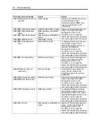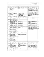
7-20 Troubleshooting
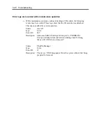
Source:
srabid
ID:
16395
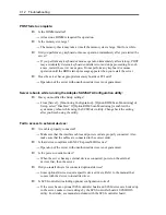
Description: XX is now STATE BROKEN/REASON_DIAGNOSTICS_FAILED
“XX” refers to the PCI module ID. If it is PCI module 1, it is shown as “10”; if it is
PCI module 2, it is shown as “11.” As to “xxxx,” the value differs depending on
circumstances when errors occur.
If the above events are recorded, follow the below prcedure to integrade the PCI
module.
(1)
Select the PCI module that failed to integrate on the ft Server Utility.
(2) Select [Clear] under [MTBF clear].
(3) Select [Start] to start the PCI module.
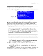
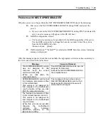
Screen under changing (distorted display) can be seen when screen resolution is
changed:
If screen resolution is changed while the entire system is under high load, screen
under changing (distorted display) may be seen.
This is because screen update is taking time to complete due to high load in the
system. This is not because an error is occuring.
The screen will return to normal if you wait awhile.
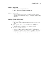
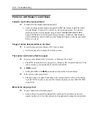
Duplexed status is not displayed properly:
When one CPU/IO module is reintegrated after the other CPU/IO module is removed
due to the failure or replacement, the status in ESMPRO or RDR Utility and status
LED 2 on the CPU/IO module may not be displayed properly.
Restore normal display with the following procedure.
<Restoration procedure>
From [Start], click [Administrative Tools] and [Services] to start Services.
Right-click [ftSys Maintenance and Diagnostics (MAD)] and click [Restart].
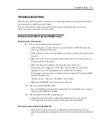
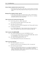
Unable to recognize the server from a managing PC:
Did you configure [Initialize Remote Management Card]?
→
Start the server-accessory EXPRESSBUILDER, then go to [Tools] - [Initialize
Remote Management Card] to write each server information in order to
initialize the card.
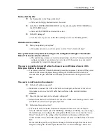
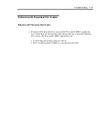
Does your management PC contain Java2 RuntimeEnvironment, Standard Edition
1.4.2_04 or later?
→
Java2 RuntimeEnvironment, Standard Edition 1.4.2_04 or later is required. Use
the following procedure to install.
Start Windows on a management PC that you want to install the Java, then
Summary of Contents for Express5800/320Fd-MR
Page 13: ...v Appendix B I O Port Addresses This appendix lists factory assigned I O port addresses...
Page 19: ...xi THIS PAGE IS INTENTIONALLY LEFT BLANK...
Page 43: ...2 10 General Description Rear View...
Page 47: ...2 14 General Description CPU IO Module CPU IO module...
Page 67: ...2 34 General Description This page is intentionally left blank...
Page 79: ...3 12 Windows Setup and Operation 3 Confirm that RDR of the disk is cancelled...
Page 106: ...Windows Setup and Operation 3 39 This page is intentionally left blank...
Page 198: ...4 92 System Configuration This page is intentionally left blank...
Page 370: ......
Page 371: ...This page is intentionally left blank...
Page 389: ...6 18 Maintenance 3 Stop of PCI module 1 4 Start of PCI module 1...
Page 391: ...6 20 Maintenance This page is intentionally left blank...
Page 465: ...System Upgrade 8 31 board must not be mixed with N8804 005 or N8803 035...
Page 480: ......
Page 483: ......

