3-42 Setup
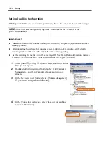
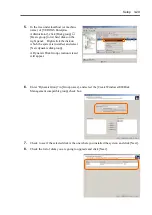
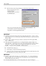
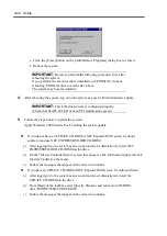
e. Click the [Close] button on the [Add/Remove Programs] dialog box to close it.
f. Reboot the system.
IMPORTANT:
Be sure to perform the following procedure No.6 after
rebooting the system
If you perform the next procedure (installation of PROSet II) without
rebooting, PROSet II does not start after reboot.
The system may become unstable.
4.
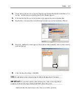
After rebooting the system, log on to the system as a user with Administrative rights.
IMPORTANT:
Check the dual system is configured properly.
(Check that STATUS2 LED of each PCI module stays green.)
5.
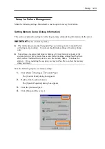
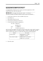
Follow the steps below to update the system:
Apply Windows 2000 Service Pack 3 during the system update.
If you do not have an UPDATE CD-ROM of NEC Express5800/ft series’ ft control
software (and use NEC EXPRESSBUILDER CD-ROM):
a) After logging in to the system as an account (such as Administrator), insert NEC
EXPRESSBUILDER CD-ROM into the drive.
b) On the “Master Controller Menu” screen that appears, click [Software Setup] and click
[System Update] on the menu.
c) Follow the messages that appear on the screen to continue.
If you have an UPDATE CD-ROM of NEC Express5800/ft series’ ft control software:
a) After logging in to the system as an account (such as Administrator), insert the
UPDATE CD-ROM into the drive.
b) From [Start] of the taskbar, select [Specify filename and run] to run CD-ROM
drive:\WINNT\W2K\UPDATE.EXE.
c) Follow the messages that appear on the screen to continue.
Summary of Contents for Express5800/320Lb FT Linux
Page 10: ...iv This page is intentionally left blank ...
Page 16: ...x This page is intentionally left blank ...
Page 19: ...Precautions for Use 1 3 Label A Label B Label C Label E Label D ...
Page 20: ...1 4 Precautions for Use Rack mount model Label B Label A Label C Label D ...
Page 21: ...Precautions for Use 1 5 Label D Label C Label B Label A ...
Page 22: ...1 6 Precautions for Use PCI CPU Modules PCI Module CPU Module Label A Label A Label A ...
Page 36: ...1 20 Precautions for Use This page is intentionally left blank ...
Page 44: ...2 8 General Description Front View inside Tower model Rack mount model ...
Page 70: ...2 34 General Description This page is intentionally left blank ...
Page 118: ...3 48 Setup This page is intentionally left blank ...
Page 162: ...4 44 System Configuration This page is intentionally left blank ...
Page 294: ...6 14 Maintenance This page is intentionally left blank ...
Page 336: ...7 42 Troubleshooting This page is intentionally left blank ...
Page 355: ...System Upgrade 8 19 15 Check the disk you selected and click Next 16 Click Complete ...
Page 399: ...System Upgrade 8 63 Cable ties included with cabinet ...
Page 410: ...8 74 System Upgrade This page is intentionally left blank ...
Page 412: ...A 2 Specifications This page is intentionally left blank ...

