System Configuration 4-41
NOTE:
After CMOS clear is completed, a message will appears for
1
0 seconds
prompting you to remove the jumper. If you select [CONTINUE] or do
nothing (considered as “CONTINUE”), the process goes on. However,
the server stops after sounding beeps (
1
-3-3-2) during POST.
This is not an error; this rechecks the presence of the jumper to prevent
you from forgetting to dismount it. In this case, power off/on the server
and continue from Step
1
0.
10.
Remove the PCI Module #
1
from the server (see Chapter 8).
11.
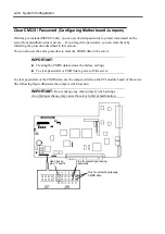
Reset the jumper switch.
TIPS:
Place the clip on the jumper pins
11
and
1
2 after use to keep the clip.
If you place it on other pins, the server may malfunction.
12.
Mount PCI Module #
1
again to the server (see Chapter 8).
13.
Mount PCI Module #2 (on which CMOS has not been cleared) to the server.
14.
Shortly after you connect the power cord, the BMC status LED of PCI Module #2 will
start to blink.
15.
When CMOS clear is completed, the BMC status LED will go off.
NOTE:
The BMC status LED blinks to show that synchronous processing is
being performed between the two modules. When this process is
complete, CMOS has also been cleared on PCI Module #2
TIPS:
For the location of the BMC status LED, see “Names and Functions
of Components” in Chapter 2.
For description of the BMC status LED, see “LED” in Chapter 2.
Summary of Contents for Express5800/320Lb FT Linux
Page 10: ...iv This page is intentionally left blank ...
Page 16: ...x This page is intentionally left blank ...
Page 19: ...Precautions for Use 1 3 Label A Label B Label C Label E Label D ...
Page 20: ...1 4 Precautions for Use Rack mount model Label B Label A Label C Label D ...
Page 21: ...Precautions for Use 1 5 Label D Label C Label B Label A ...
Page 22: ...1 6 Precautions for Use PCI CPU Modules PCI Module CPU Module Label A Label A Label A ...
Page 36: ...1 20 Precautions for Use This page is intentionally left blank ...
Page 44: ...2 8 General Description Front View inside Tower model Rack mount model ...
Page 70: ...2 34 General Description This page is intentionally left blank ...
Page 118: ...3 48 Setup This page is intentionally left blank ...
Page 162: ...4 44 System Configuration This page is intentionally left blank ...
Page 294: ...6 14 Maintenance This page is intentionally left blank ...
Page 336: ...7 42 Troubleshooting This page is intentionally left blank ...
Page 355: ...System Upgrade 8 19 15 Check the disk you selected and click Next 16 Click Complete ...
Page 399: ...System Upgrade 8 63 Cable ties included with cabinet ...
Page 410: ...8 74 System Upgrade This page is intentionally left blank ...
Page 412: ...A 2 Specifications This page is intentionally left blank ...

