5-2 Installing and Using Utilities
NEC EXPRESSBUILDER
The NEC EXPRESSBUILDER, integrated setup software, can automatically detect the hardware
connected to an NEC Express5800/ft series machine to advance the processing. The hardware
subject to setup with the NEC EXPRESSBUILDER should have the same configuration as that for
operation.
Start Menu
The NEC EXPRESSBUILDER provides three procedures to start the server as described below. The
menus and items appearing on the screen vary depending on the procedures.
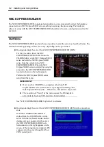
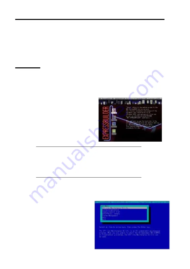
Booting (starting) the server from NEC EXPRESSBUILDER CD-ROM
For the procedure, insert the NEC
EXPRESSBUILDER CD-ROM into the
CD-ROM drive of the NEC Express5800/ft
series and start the NEC Express5800/ft
series from the system in the NEC
EXPRESSBUILDER. When the NEC
Express5800/ft series is started by using this
procedure, the NEC EXPRESSBUILDER
top menu shown on the right appears.
Perform the NEC Express5800/ft series
setup from this menu.
IMPORTANT:
Don’t use this CD-ROM on computers other than NEC
Express5800/ft series with which it is packaged (including other
NEC Express5800 models). Otherwise, a breakdown may result.
The execution of "Setup" of the menu causes the OS installed
previously to be erased. OS must also be reinstalled.
See "NEC EXPRESSBUILDER Top Menu" for details.
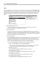
Booting (starting) the server from NEC EXPRESSBUILDER CD-ROM in the consoleless
state
If the NEC EXPRESSBUILDER is
started from the CD-ROM drive in the
server with the keyboard, mouse, and/or
display unit not connected to the server,
the NEC EXPRESSBUILDER Tools
Menu shown on the right appears on the
screen of the management computer (PC)
connected to the server through LAN or
COM (serial port).
Summary of Contents for Express5800/320Lb FT Linux
Page 10: ...iv This page is intentionally left blank ...
Page 16: ...x This page is intentionally left blank ...
Page 19: ...Precautions for Use 1 3 Label A Label B Label C Label E Label D ...
Page 20: ...1 4 Precautions for Use Rack mount model Label B Label A Label C Label D ...
Page 21: ...Precautions for Use 1 5 Label D Label C Label B Label A ...
Page 22: ...1 6 Precautions for Use PCI CPU Modules PCI Module CPU Module Label A Label A Label A ...
Page 36: ...1 20 Precautions for Use This page is intentionally left blank ...
Page 44: ...2 8 General Description Front View inside Tower model Rack mount model ...
Page 70: ...2 34 General Description This page is intentionally left blank ...
Page 118: ...3 48 Setup This page is intentionally left blank ...
Page 162: ...4 44 System Configuration This page is intentionally left blank ...
Page 294: ...6 14 Maintenance This page is intentionally left blank ...
Page 336: ...7 42 Troubleshooting This page is intentionally left blank ...
Page 355: ...System Upgrade 8 19 15 Check the disk you selected and click Next 16 Click Complete ...
Page 399: ...System Upgrade 8 63 Cable ties included with cabinet ...
Page 410: ...8 74 System Upgrade This page is intentionally left blank ...
Page 412: ...A 2 Specifications This page is intentionally left blank ...

