5-58 Installing and Using Utilities
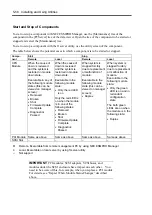
Start and Stop of Components
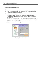
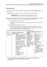
To start or stop a component with NEC ESMPRO Manager, use the [Maintenance] tree of the
component in the [FTServer] tree of the data viewer. Open the tree of the component to be started or
stopped and select the [Maintenance] tree.
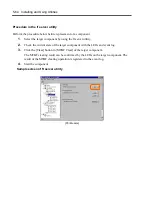
To start or stop a component with the ft server utility, use the utility screen of the component.
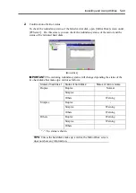
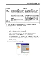
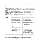
The table below shows the potential cases in which a component is to be started or stopped.
Start Stop
Compo-
nent
Remote Local
Remote
Local
CPU
Module
When the cause of
down is reviewed
and the system is
restarted in module
down state.
Executable in any of
the following module
states (this can be
viewed on manager
screen):
•
Removed
•
Broken
•
Shot
•
Firmware Update
Complete
•
Diagnostics
Passed
When the cause of
down is reviewed
and the system is
restarted in module
down state.
Executable in the
following module
state:
•
Only the red LED
is on
Only the red LED is
on when the module
is in one of the
following states:
•
Removed
•
Broken
•
Shot
•
Firmware Update
Complete
•
Diagnostics
Passed
When system is
stopped forcibly
due to replacement
or malfunction of
module.
Executable in the
following module
state (this can be
viewed on manager
screen):
•
Duplex
When system is
stopped forcibly
due to replacement
or malfunction of
module.
Executable in the
following module
state:
•
Only the green
LED is on and in
redundant
configuration
state
The both green
LEDs are on when
the module is in the
following state:
•
Duplex
PCI Module Same as above
Same as above
Same as above
Same as above
SCSI Slot
–
–
–
–
R:
Remote. Executable from remote management PC by using NEC ESMPRO Manager
L:
Local. Executable on local server by using ft server utility
–: Not
support
IMPORTANT:
PCI modules, SCSI adapters, SCSI buses, and
modules under the SCSI enclosure have impact on each other. You
need to be aware of this, for example, when you replace a PCI module.
For details, see “Impact When Module Status Changes” described
above.
Summary of Contents for Express5800/320Lb FT Linux
Page 10: ...iv This page is intentionally left blank ...
Page 16: ...x This page is intentionally left blank ...
Page 19: ...Precautions for Use 1 3 Label A Label B Label C Label E Label D ...
Page 20: ...1 4 Precautions for Use Rack mount model Label B Label A Label C Label D ...
Page 21: ...Precautions for Use 1 5 Label D Label C Label B Label A ...
Page 22: ...1 6 Precautions for Use PCI CPU Modules PCI Module CPU Module Label A Label A Label A ...
Page 36: ...1 20 Precautions for Use This page is intentionally left blank ...
Page 44: ...2 8 General Description Front View inside Tower model Rack mount model ...
Page 70: ...2 34 General Description This page is intentionally left blank ...
Page 118: ...3 48 Setup This page is intentionally left blank ...
Page 162: ...4 44 System Configuration This page is intentionally left blank ...
Page 294: ...6 14 Maintenance This page is intentionally left blank ...
Page 336: ...7 42 Troubleshooting This page is intentionally left blank ...
Page 355: ...System Upgrade 8 19 15 Check the disk you selected and click Next 16 Click Complete ...
Page 399: ...System Upgrade 8 63 Cable ties included with cabinet ...
Page 410: ...8 74 System Upgrade This page is intentionally left blank ...
Page 412: ...A 2 Specifications This page is intentionally left blank ...

