Installing and Using Utilities 5-65
Diagnostics
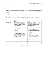
The NEC Express5800/ft series provides the self-check diagnosis function for some components. If
a fault occurs in a component, the NEC Express5800/ft series can diagnose the component to detect
the fault.
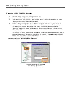
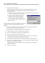
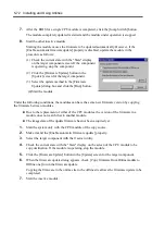
To diagnose a component with the NEC ESMPRO Manager, use the [Maintenance] tree of the
component in the data viewer. Open the tree of the component to be diagnosed and select the
[Maintenance] tree.
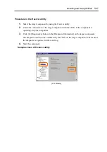
To diagnose of a component with the ft server utility, use the utility screen of the component.
The table below shows the potential cases in which a component is to be diagnosed.
Diagnosis
Component
Remote Local
CPU Module
When a phenomenon causing the
module to be down occurs or a
phenomenon supposed to be a
malfunction occurs.
Executable in any of the following
module states (this can be viewed on
manager screen):
•
Removed
•
Broken
•
Shot
•
Firmware Update Complete
To diagnose the module under
operation, bring down the module
before the diagnosis.
When a phenomenon causing the
module to be down occurs or a
phenomenon supposed to be a
malfunction occurs.
Executable in any of the following
module states:
•
Only the red LED is on
Only the red LED is on when the
module is in one the following states:
•
Removed
•
Broken
•
Shot
•
Firmware Update Complete
(no fault found by diagnosis)
To diagnose the module under
operation, bring down the module
before the diagnosis.
PCI Module
Same as above
Same as above
R: Remote. Executable from remote management PC by using NEC ESMPRO Manager
L: Local. Executable on local server by using ft server utility
–: Not
support
Summary of Contents for Express5800/320Lb FT Linux
Page 10: ...iv This page is intentionally left blank ...
Page 16: ...x This page is intentionally left blank ...
Page 19: ...Precautions for Use 1 3 Label A Label B Label C Label E Label D ...
Page 20: ...1 4 Precautions for Use Rack mount model Label B Label A Label C Label D ...
Page 21: ...Precautions for Use 1 5 Label D Label C Label B Label A ...
Page 22: ...1 6 Precautions for Use PCI CPU Modules PCI Module CPU Module Label A Label A Label A ...
Page 36: ...1 20 Precautions for Use This page is intentionally left blank ...
Page 44: ...2 8 General Description Front View inside Tower model Rack mount model ...
Page 70: ...2 34 General Description This page is intentionally left blank ...
Page 118: ...3 48 Setup This page is intentionally left blank ...
Page 162: ...4 44 System Configuration This page is intentionally left blank ...
Page 294: ...6 14 Maintenance This page is intentionally left blank ...
Page 336: ...7 42 Troubleshooting This page is intentionally left blank ...
Page 355: ...System Upgrade 8 19 15 Check the disk you selected and click Next 16 Click Complete ...
Page 399: ...System Upgrade 8 63 Cable ties included with cabinet ...
Page 410: ...8 74 System Upgrade This page is intentionally left blank ...
Page 412: ...A 2 Specifications This page is intentionally left blank ...

