5-86 Installing and Using Utilities
NEC MWA
∼∼∼∼
Management Workstation Application
∼∼∼∼
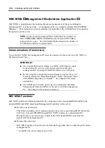
NEC MWA is an application that enables the remote management of the server through a
management PC over the network. (A management PC is a computer running NEC ESMPRO
Manager.) This application assists in reducing responsibility of the Administrator for managing
the operation of the server.
TIPS:
See the online documented "NEC MWA First Step Guide" in
NEC EXPRESSBUILDER CD-ROM for the details on NEC MWA
setup and how to use. See NEC MWA Online Help for the details on
the functions and how to operate them.
Communications (Connection)
To use the NEC MWA, the management PC must be connected to the server via LAN, WAN or
COM port (Serial Port.)
IMPORTANT:
The Console Redirection feature (via WAN or COM port) cannot
be used when the server is operated remotely from the other
management PC by using the RomPilot feature (via LAN port).
Before using the Console Redirection feature to operate the server
remotely, change the "RomPilot Support" in the "Advanced" menu
of the BIOS setup utility to "disable". See Chapter 4 for detail
explanation.
The COM2 port or LAN1 port is used to communicate the Base
Management Controller (BMC) in the server with the management
PC. See Chapter 2 for connector location.
NEC MWA Functions
NEC MWA enables the following functions by connecting to the extended BIOS (RomPilot), the
standard BIOS and BMC (Baseboard Management Controller) of the server.
Remote console function
This function enables you to remotely monitor the server screen during POST (Power On
Self-Test) or booted MS-DOS through NEC MWA window on a management PC.
During the time, you can also key in data to the NEC Express5800 series from the
keyboard of the management PC.
Remote drive function*
NEC MWA enables to boot the servers from the floppy disk drive or disk image file on the
management PC.
* Available only when connected via LAN.
Summary of Contents for Express5800/320Lb FT Linux
Page 10: ...iv This page is intentionally left blank ...
Page 16: ...x This page is intentionally left blank ...
Page 19: ...Precautions for Use 1 3 Label A Label B Label C Label E Label D ...
Page 20: ...1 4 Precautions for Use Rack mount model Label B Label A Label C Label D ...
Page 21: ...Precautions for Use 1 5 Label D Label C Label B Label A ...
Page 22: ...1 6 Precautions for Use PCI CPU Modules PCI Module CPU Module Label A Label A Label A ...
Page 36: ...1 20 Precautions for Use This page is intentionally left blank ...
Page 44: ...2 8 General Description Front View inside Tower model Rack mount model ...
Page 70: ...2 34 General Description This page is intentionally left blank ...
Page 118: ...3 48 Setup This page is intentionally left blank ...
Page 162: ...4 44 System Configuration This page is intentionally left blank ...
Page 294: ...6 14 Maintenance This page is intentionally left blank ...
Page 336: ...7 42 Troubleshooting This page is intentionally left blank ...
Page 355: ...System Upgrade 8 19 15 Check the disk you selected and click Next 16 Click Complete ...
Page 399: ...System Upgrade 8 63 Cable ties included with cabinet ...
Page 410: ...8 74 System Upgrade This page is intentionally left blank ...
Page 412: ...A 2 Specifications This page is intentionally left blank ...

