5-90 Installing and Using Utilities
Connect from the Management PC Linked through LAN
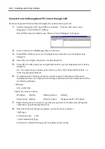
On the management PC that is linked through LAN, perform the steps below:
1.
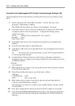
Start the management PC where MWA is installed. From the Start menu, select
[Program]
→
[NEC MWA]
→
[MWA].
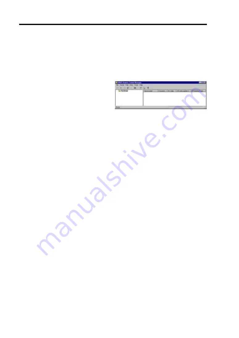
When MWA starts, the initial screen “Remote Control Manager” will appear.
2.
Insert a formatted 1.44MB floppy disk into the drive.
3.
From MWA’s [File] menu, select [Configuration] command to open [Configuration]
dialog box.
4.
Select [New] to display the [Select a model] dialog box.
5.
Check [Write to FD] and select an applicable model to open [Configuration for ft Series]
dialog box.
Ex) The model name is printed on the front cover like “NEC Express5800/320Lb,” or
“NEC Express5800/320Lb-R.”
6.
[Configuration for ft Series] dialog box, specify/register configuration information
including the names of computers to be managed, and then write the information to FD as
the following filename:
<Filename>
CSL_LESS.CFG
Specify the items as follows:
IP address:
arbitrary
Default gateway:
arbitrary
Subnet mask: arbitrary
Primary contact:
Management PC’s IP address
7.
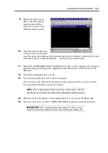
Right-clicking the server name to open the pop-up menu, from which select [Property]
command to open [Property] dialog box.
8.
When the [Property] dialog box appears: specify the items as follows:
<[ID] page>
Connection mode:
LAN
<[Alert notification] page>
Uncheck [Use Default Settings] and check [Reset] of [Activate].
Summary of Contents for Express5800/320Lb FT Linux
Page 10: ...iv This page is intentionally left blank ...
Page 16: ...x This page is intentionally left blank ...
Page 19: ...Precautions for Use 1 3 Label A Label B Label C Label E Label D ...
Page 20: ...1 4 Precautions for Use Rack mount model Label B Label A Label C Label D ...
Page 21: ...Precautions for Use 1 5 Label D Label C Label B Label A ...
Page 22: ...1 6 Precautions for Use PCI CPU Modules PCI Module CPU Module Label A Label A Label A ...
Page 36: ...1 20 Precautions for Use This page is intentionally left blank ...
Page 44: ...2 8 General Description Front View inside Tower model Rack mount model ...
Page 70: ...2 34 General Description This page is intentionally left blank ...
Page 118: ...3 48 Setup This page is intentionally left blank ...
Page 162: ...4 44 System Configuration This page is intentionally left blank ...
Page 294: ...6 14 Maintenance This page is intentionally left blank ...
Page 336: ...7 42 Troubleshooting This page is intentionally left blank ...
Page 355: ...System Upgrade 8 19 15 Check the disk you selected and click Next 16 Click Complete ...
Page 399: ...System Upgrade 8 63 Cable ties included with cabinet ...
Page 410: ...8 74 System Upgrade This page is intentionally left blank ...
Page 412: ...A 2 Specifications This page is intentionally left blank ...


