6-8 Maintenance
5.
Select [Tool].
6.
Select [System Diagnostics].
Thesystem diagnosus starts and will be
completed in approximately three minutes.
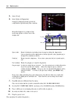
When the diagnosis is completed, the
following appears on the screen of the
display unit.
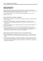
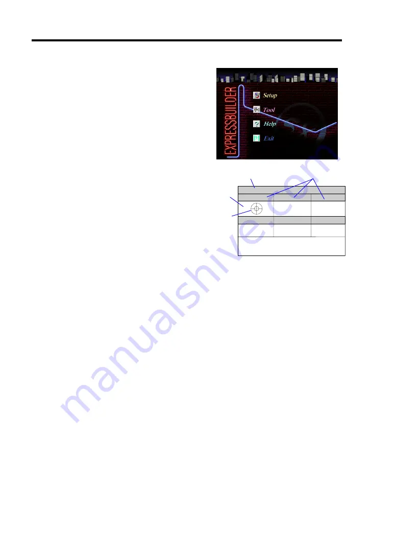
System bar:
Shows information including time of progress during the diagnostics.
Upon completion of the diagnostics, and descriptions on key operations to
navigate the windoware shown.
Title bar:
Shows items for diagnosis. If an error is detected, the bar is indicated in
red.
Test window: Shows the progress or result of diagnostics.
Target scope: A cursor to select the test window. Use the cursor keys on the keyboard to
move it to another test window. (Move the target scope to a desired
window and press
Enter
. Now you can view detailed information on the
selected window. To return to the previous window, press
Enter
once
again.)
If an error is detected during the system diagnostics, the title bar turns in red, and error
information is displayed in red characters. Note down the error message and contact
your sales agent.
7.
Press
Q
and select [Reboot] from the menu.
The server restarts and the system is started from the NEC EXPRESSBUILDER.
8.
Exit the NEC EXPRESSBUILDER, and remove the CD-ROM from the CD-ROM drive.
9.
Power off the server and unplug the power cord from the receptacle.
10.
Reconnect all the LAN cables to the server.
11.
Plug the power cord.
This completes the system diagnostics.
CURSOR: Select Window ENTER: View Window P: Log Out Q: Quit
Target scope
Test window
System bar
Title bar
Summary of Contents for Express5800/320Lb FT Linux
Page 10: ...iv This page is intentionally left blank ...
Page 16: ...x This page is intentionally left blank ...
Page 19: ...Precautions for Use 1 3 Label A Label B Label C Label E Label D ...
Page 20: ...1 4 Precautions for Use Rack mount model Label B Label A Label C Label D ...
Page 21: ...Precautions for Use 1 5 Label D Label C Label B Label A ...
Page 22: ...1 6 Precautions for Use PCI CPU Modules PCI Module CPU Module Label A Label A Label A ...
Page 36: ...1 20 Precautions for Use This page is intentionally left blank ...
Page 44: ...2 8 General Description Front View inside Tower model Rack mount model ...
Page 70: ...2 34 General Description This page is intentionally left blank ...
Page 118: ...3 48 Setup This page is intentionally left blank ...
Page 162: ...4 44 System Configuration This page is intentionally left blank ...
Page 294: ...6 14 Maintenance This page is intentionally left blank ...
Page 336: ...7 42 Troubleshooting This page is intentionally left blank ...
Page 355: ...System Upgrade 8 19 15 Check the disk you selected and click Next 16 Click Complete ...
Page 399: ...System Upgrade 8 63 Cable ties included with cabinet ...
Page 410: ...8 74 System Upgrade This page is intentionally left blank ...
Page 412: ...A 2 Specifications This page is intentionally left blank ...

