Troubleshooting 7-37
Collection of the Memory Dump
If a failure occurs, the memory data should be dumped to acquire the required information. If you
stored the dump data in a DAT, label it so as to indicate the software (e.g. NTBackup) you used for
storing it. You may save the diagnosis data to a desired destination.
IMPORTANT:
Consult with your sales agent before dumping the memory. Executing memory
dumping while the server is in the normal operation may affect the system
operation.
Restarting the system due to an error may display a message indicating
insufficient virtual memory. Ignore this message and proceed. Restarting the
system again may result in dumping improper data.
Preparing for Memory Dump
Memory dumping with the DUMP switch may disable the server to restart. In such a case, it is
required to force the server to shut down. This forced shutdown, however, is not available if
"Masked" is selected for "Power Switch Mask" on the Security menu of the BIOS setup utility,
SETUP, because this setting disables POWER switch operation.
Follow the procedure below to change the setting to enable the forced shutdown and restart of the
server.
1.
Power on the server and start the BIOS setup utility, SETUP.
2.
Select "Unmasked" for "Power Switch Mask" in the Security menu.
3.
Save the configuration data and exit the SETUP.
Saving Dump Files
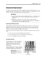
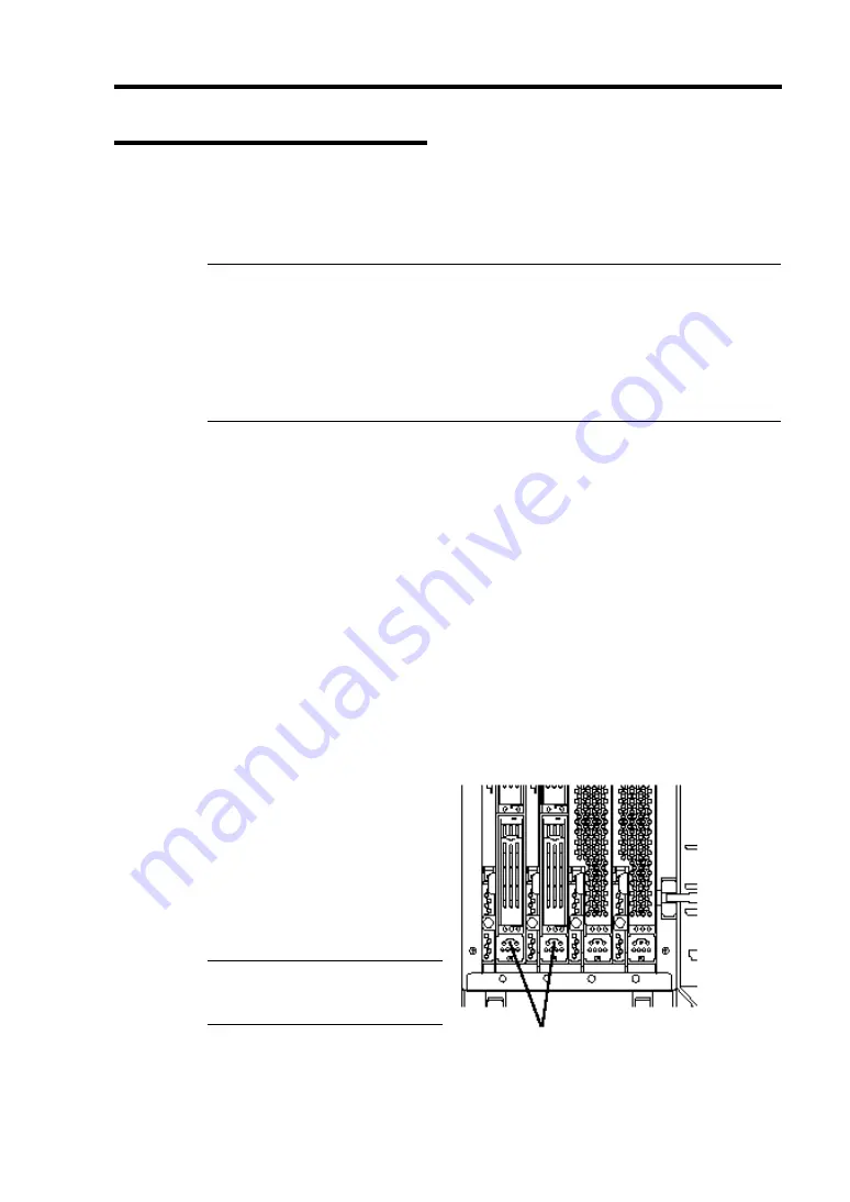
Press the DUMP switch to save the dump file
when an error occurs. Insert a metal pin (a
straightened large paper clip will make a
substitute) into the switch hole to press the
DUMP switch.
Pressing the DUMP switch saves the dump file
in the specified directory. (Memory dumping
may not be available when the CPU stalls.)
IMPORTANT:
Do not use a
toothpick or plastic stick that is
easy to break.
Dump switches
Summary of Contents for Express5800/320Lb FT Linux
Page 10: ...iv This page is intentionally left blank ...
Page 16: ...x This page is intentionally left blank ...
Page 19: ...Precautions for Use 1 3 Label A Label B Label C Label E Label D ...
Page 20: ...1 4 Precautions for Use Rack mount model Label B Label A Label C Label D ...
Page 21: ...Precautions for Use 1 5 Label D Label C Label B Label A ...
Page 22: ...1 6 Precautions for Use PCI CPU Modules PCI Module CPU Module Label A Label A Label A ...
Page 36: ...1 20 Precautions for Use This page is intentionally left blank ...
Page 44: ...2 8 General Description Front View inside Tower model Rack mount model ...
Page 70: ...2 34 General Description This page is intentionally left blank ...
Page 118: ...3 48 Setup This page is intentionally left blank ...
Page 162: ...4 44 System Configuration This page is intentionally left blank ...
Page 294: ...6 14 Maintenance This page is intentionally left blank ...
Page 336: ...7 42 Troubleshooting This page is intentionally left blank ...
Page 355: ...System Upgrade 8 19 15 Check the disk you selected and click Next 16 Click Complete ...
Page 399: ...System Upgrade 8 63 Cable ties included with cabinet ...
Page 410: ...8 74 System Upgrade This page is intentionally left blank ...
Page 412: ...A 2 Specifications This page is intentionally left blank ...


