7-40 Troubleshooting
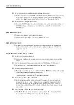
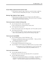
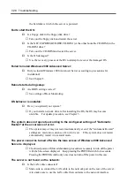
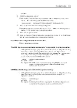
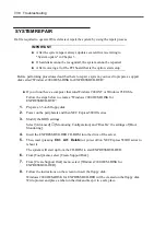
In the steps below, repair the system using information inside the disk instead of a system
repair disk:
1.
Modify the BIOS settings.
Select [Advanced]
→
[Monitoring Configuration], and “Disable” the setting of [Boot
Monitoring]. For details, see Chapter 4 "Monitoring Configuration".
2.
Power on the system.
3.
Insert the Windows 2000 Advanced Server CD-ROM into the drive of the server.
4.
Then, reset (pressing
Ctrl
+
Alt
+
Delete
) or power off/on NEC Express5800/ft series to
reboot it.
5.
Wait until message "Press any key to boot from CD" appears on the screen.
6.
Press any key to select the start from CD-ROM.
IMPORTANT:
Unless an arbitrary key is pressed during the display of
the message, the system is started from the hard disk drive. The repair
process cannot be started.
7.
Wait until message "Press F6 if…" appears on the screen.
8.
Press the
F5
and
F6
quickly.
IMPORTANT:
If you press neither the
F5
nor
F6
, the repair process is
not started.
9.
If the text-base setup is started, follow the directions on the screen to proceed.
As you follow the directions, the screen for selecting HAL will appear.
10.
Insert the Windows 2000 OEM-DISK for EXPRESSBUILDER into the floppy disk drive
and specify the module saved in the OEM disk.
As you follow the directions, the screen for selecting the SCSI driver will appear.
11.
Insert the Windows 2000 OEM-DISK for EXPRESSBUILDER into the floppy disk drive
and specify the SCSI driver saved in the OEM disk.
As you follow the directions, the screen for selecting the SCSI driver will appear.
NOTE:
The OEM disk contains more than one SCSI driver. Press
S
to
select all the SCSI drivers.
Message "Press R key to repair Windows 2000 already installed" appears.
12.
Press
R
to select the repair option.
13.
Select the type of the keyboard.
Summary of Contents for Express5800/320Lb FT Linux
Page 10: ...iv This page is intentionally left blank ...
Page 16: ...x This page is intentionally left blank ...
Page 19: ...Precautions for Use 1 3 Label A Label B Label C Label E Label D ...
Page 20: ...1 4 Precautions for Use Rack mount model Label B Label A Label C Label D ...
Page 21: ...Precautions for Use 1 5 Label D Label C Label B Label A ...
Page 22: ...1 6 Precautions for Use PCI CPU Modules PCI Module CPU Module Label A Label A Label A ...
Page 36: ...1 20 Precautions for Use This page is intentionally left blank ...
Page 44: ...2 8 General Description Front View inside Tower model Rack mount model ...
Page 70: ...2 34 General Description This page is intentionally left blank ...
Page 118: ...3 48 Setup This page is intentionally left blank ...
Page 162: ...4 44 System Configuration This page is intentionally left blank ...
Page 294: ...6 14 Maintenance This page is intentionally left blank ...
Page 336: ...7 42 Troubleshooting This page is intentionally left blank ...
Page 355: ...System Upgrade 8 19 15 Check the disk you selected and click Next 16 Click Complete ...
Page 399: ...System Upgrade 8 63 Cable ties included with cabinet ...
Page 410: ...8 74 System Upgrade This page is intentionally left blank ...
Page 412: ...A 2 Specifications This page is intentionally left blank ...

