8-4 System Upgrade
PREPARING YOUR SYSTEM FOR UPGRADE
Note the followings, when installing or replacing devices, to improve the performance of NEC
Express5800/ft series.
With the NEC Express5800/ft series server, devices can be replaced during the continuous
operation. Take extreme care for electric shock and damage to the component due to
short-circuit.
Optional devices cannot be installed or removed during continuous operation. Normally,
shutdown Windows 2000 Advanced Server, check that the server is powered off,
disconnect all power cords and interface cables from the server before installing or
removing the optional devices.
To remove the CPU or PCI module during the continuous operation, disable the intended
module (place the module off-line) by using the ft series utility of the NEC ESMPRO
Agent or the NEC ESMPRO Manager from the management PC on the network. After a
new module is installed to the server, enable the module using the ft series utility or the
NEC ESMPRO Manager.
NOTE:
The system is defaulted to automatically boot the module, once
installed. This setting can be changed with the ft series utility or the
NEC ESMPRO Manager. For more information, see Chapter 5.
Make sure to provide the same hardware configuration on both groups.
Use the same slots and sockets on both groups.
Do not install those devices having different specifications, performance, or features.
Before removing the setscrews from the CPU and PCI modules, place the desired module
off-line using the ft series utility or the NEC ESMPRO Manager.
Summary of Contents for Express5800/320Lb FT Linux
Page 10: ...iv This page is intentionally left blank ...
Page 16: ...x This page is intentionally left blank ...
Page 19: ...Precautions for Use 1 3 Label A Label B Label C Label E Label D ...
Page 20: ...1 4 Precautions for Use Rack mount model Label B Label A Label C Label D ...
Page 21: ...Precautions for Use 1 5 Label D Label C Label B Label A ...
Page 22: ...1 6 Precautions for Use PCI CPU Modules PCI Module CPU Module Label A Label A Label A ...
Page 36: ...1 20 Precautions for Use This page is intentionally left blank ...
Page 44: ...2 8 General Description Front View inside Tower model Rack mount model ...
Page 70: ...2 34 General Description This page is intentionally left blank ...
Page 118: ...3 48 Setup This page is intentionally left blank ...
Page 162: ...4 44 System Configuration This page is intentionally left blank ...
Page 294: ...6 14 Maintenance This page is intentionally left blank ...
Page 336: ...7 42 Troubleshooting This page is intentionally left blank ...
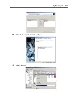
Page 355: ...System Upgrade 8 19 15 Check the disk you selected and click Next 16 Click Complete ...
Page 399: ...System Upgrade 8 63 Cable ties included with cabinet ...
Page 410: ...8 74 System Upgrade This page is intentionally left blank ...
Page 412: ...A 2 Specifications This page is intentionally left blank ...


