8-14 System Upgrade
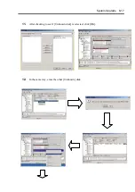
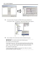
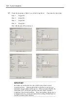
How to Restore Redundant Configuration Manually
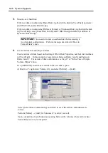
If the system does not restore the redundant configuration automatically after you replace the failed
disks, follow the steps below to restore the configuration manually:
IMPORTANT:
The redundant configuration is not restored
automatically in the following cases:
If you use a signed hard disk.
If you replace a disk that is connected to a fibre channel.
If you replace a disk that has partitions or volumes.
If you replace a disk while the system is shut down.
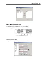
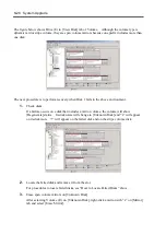
This section describes procedures to re-establish the dual configuration of hard disks whose
volumes are created by VERITAS Volume Manager at the time of failure recovery. Although
there are procedures for simple volume, stripe volume, and span volume, see “In the Case of Simple
Volume Mirroring” for the basic procedure.
IMPORTANT:
If you need to remove a hard disk due to a failure, identify that hard
disk on Data Viewer, not the disk number on [VERITAS Enterprise
Administrator].
When you make resetting of the mirrors, see the target IDs of
[Device types] listed in [Properties], not the disk numbers on
[VERITAS Enterprise Administrator].
If a hard disk included a Boot volume (if it was used to store OS),
you cannot use it in a dual disk configuration (you cannot import it
by [Import dynamic group] command). You need to format the
disk before using it in a dual configuration.
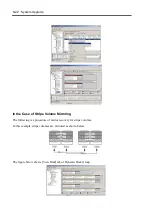
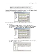
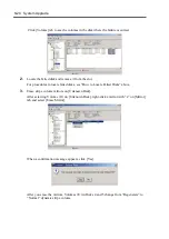
In the Case of Simple Volume Mirroring
The following steps use the example described in Section “How to Locate Failed Disks” above,
where the second disk of Group 1 (in Slot#2) and the third disk of Group 2 (in Slot#3) failed.
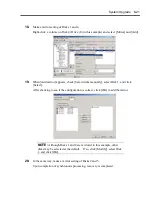
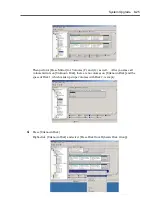
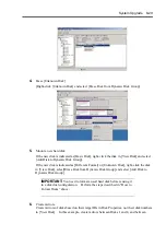
1.
In [Start] menu, click [Setting] and [Control Panel].
[Control Panel] window will appear.
2.
Double-click [Management Tools] icon.
[Management Tools] window will appear.
3.
Double-click [Computer Management] icon.
[Management Tools] window will appear.
Summary of Contents for Express5800/320Lb FT Linux
Page 10: ...iv This page is intentionally left blank ...
Page 16: ...x This page is intentionally left blank ...
Page 19: ...Precautions for Use 1 3 Label A Label B Label C Label E Label D ...
Page 20: ...1 4 Precautions for Use Rack mount model Label B Label A Label C Label D ...
Page 21: ...Precautions for Use 1 5 Label D Label C Label B Label A ...
Page 22: ...1 6 Precautions for Use PCI CPU Modules PCI Module CPU Module Label A Label A Label A ...
Page 36: ...1 20 Precautions for Use This page is intentionally left blank ...
Page 44: ...2 8 General Description Front View inside Tower model Rack mount model ...
Page 70: ...2 34 General Description This page is intentionally left blank ...
Page 118: ...3 48 Setup This page is intentionally left blank ...
Page 162: ...4 44 System Configuration This page is intentionally left blank ...
Page 294: ...6 14 Maintenance This page is intentionally left blank ...
Page 336: ...7 42 Troubleshooting This page is intentionally left blank ...
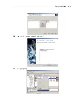
Page 355: ...System Upgrade 8 19 15 Check the disk you selected and click Next 16 Click Complete ...
Page 399: ...System Upgrade 8 63 Cable ties included with cabinet ...
Page 410: ...8 74 System Upgrade This page is intentionally left blank ...
Page 412: ...A 2 Specifications This page is intentionally left blank ...


