System Upgrade 8-31
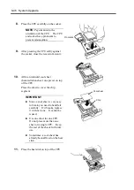
CPU MODULE
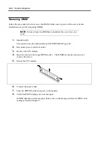
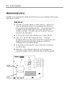
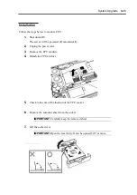
Concerning the CPU module, you can add or replace the following components, or CRU
(customer-replaceable units):
CPU (processor)
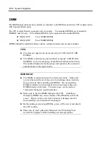
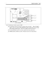
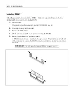
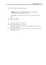
DIMM (memory)
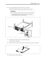
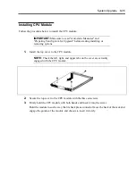
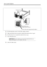
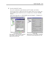
Remove the CPU module to install or remove these devices. The figures used in this section show
the tower model. The orientation is the only difference from the rack-mount model.
IMPORTANT:
Ask your sales agent to replace the CPU module and components of
the PCI module.
Make sure to read "Anti-static Measures" and "Preparing Your
System for Upgrade" before installing or removing options.
To install or remove CPU or DIMM, first power off the server
before removing the CPU module. The procedures described
below are for replacement of DIMMs.
Removing the module being operating may cause unexpected
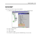
trouble. Use the management software (e.g., ft series utility or NEC
ESMPRO Manager) to identify the module to be removed so that
the module is removed when it is stopped, without fail
Then remove the relevant module after verifying the status LED on
the CPU module.
Handle the module fixing screw with your hand, not by using any
tool.
If you have replaced the module, attach an HDD ID label indicating
the replaced module number to the upper part of the fixing screw of
the module.
Summary of Contents for Express5800/320Lb FT Linux
Page 10: ...iv This page is intentionally left blank ...
Page 16: ...x This page is intentionally left blank ...
Page 19: ...Precautions for Use 1 3 Label A Label B Label C Label E Label D ...
Page 20: ...1 4 Precautions for Use Rack mount model Label B Label A Label C Label D ...
Page 21: ...Precautions for Use 1 5 Label D Label C Label B Label A ...
Page 22: ...1 6 Precautions for Use PCI CPU Modules PCI Module CPU Module Label A Label A Label A ...
Page 36: ...1 20 Precautions for Use This page is intentionally left blank ...
Page 44: ...2 8 General Description Front View inside Tower model Rack mount model ...
Page 70: ...2 34 General Description This page is intentionally left blank ...
Page 118: ...3 48 Setup This page is intentionally left blank ...
Page 162: ...4 44 System Configuration This page is intentionally left blank ...
Page 294: ...6 14 Maintenance This page is intentionally left blank ...
Page 336: ...7 42 Troubleshooting This page is intentionally left blank ...
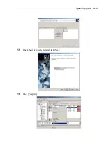
Page 355: ...System Upgrade 8 19 15 Check the disk you selected and click Next 16 Click Complete ...
Page 399: ...System Upgrade 8 63 Cable ties included with cabinet ...
Page 410: ...8 74 System Upgrade This page is intentionally left blank ...
Page 412: ...A 2 Specifications This page is intentionally left blank ...

