8-32 System Upgrade
Removing CPU Module
Follow the procedure below to remove the CPU module.
1.
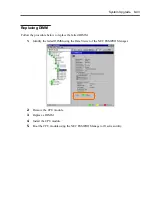
Stop the CPU module you want to remove.
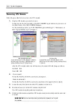
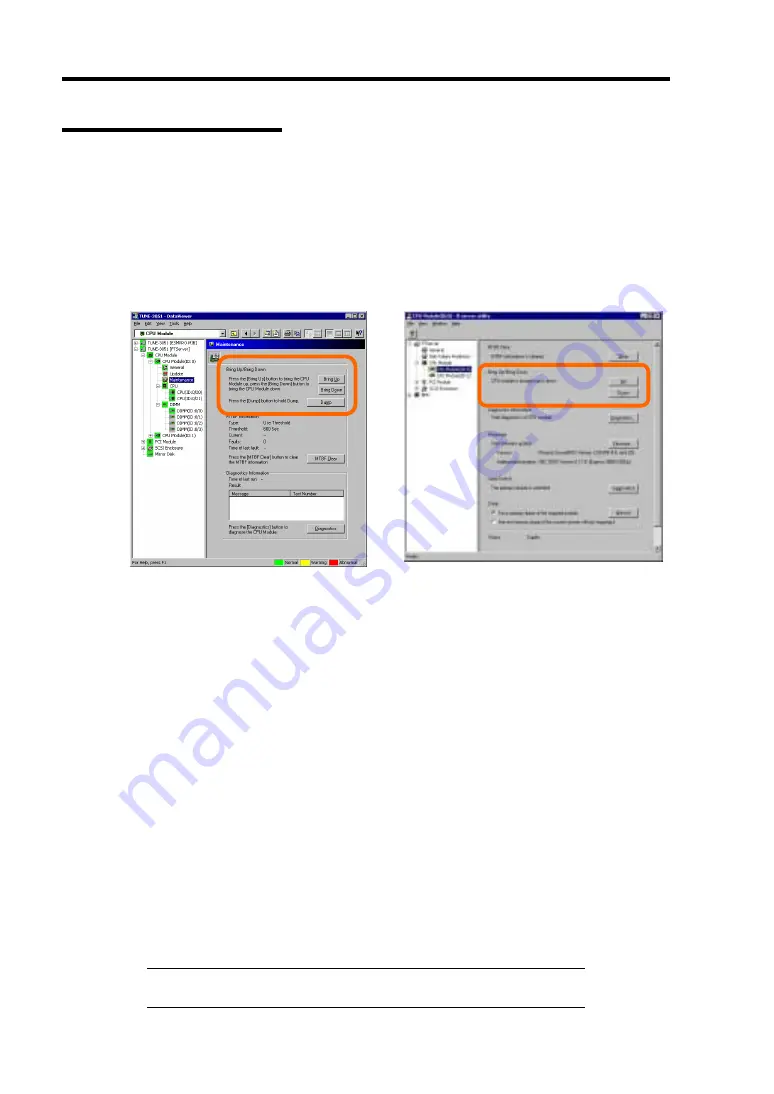
To this end, use the ft series utility of the NEC ESMPRO Agent installed to your server or
the Data Viewer of the NEC ESMPRO Manager.
For the detailed procedure, see "NEC ESMPRO Agent and Manager" - "Maintenance of
NEC Express5800/ft series" in Chapter 5.
NEC ESMPRO Manager
Select [FTServer]
→
[CPU Module]
→
[[*]CPU
Module (to be removed)]
→
[Maintenance]
→
[Bring Up/Bring Down]
→
[Bring Down].
ft series utility
Select [FTServer]
→
[CPU Module]
→
[CPU
Module (to be removed)]
→
[Bring Up/Bring Down]
→
[Down].
After the CPU module enters into off-line status, the status LED will change as follows.
Fail LED: Red
State LED: Off
2.
<Tower model>
Unlock the front bezel with the security key and open it.
<Rack-mount model>
Unlock the front bezel with the security key and remove the upper and lower panels.
3.
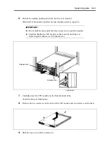
Loosen the setscrews that secured the CPU module’s release lever.
4.
Hold the release lever of the CPU module and pull it off.
The CPU module is slightly pulled out toward you.
5.
Firmly hold the handle and pull the CPU module slowly and carefully until the main unit
is locked.
IMPORTANT:
Do not hold the other parts than the release lever to pull
the module.
Summary of Contents for Express5800/320Lb FT Linux
Page 10: ...iv This page is intentionally left blank ...
Page 16: ...x This page is intentionally left blank ...
Page 19: ...Precautions for Use 1 3 Label A Label B Label C Label E Label D ...
Page 20: ...1 4 Precautions for Use Rack mount model Label B Label A Label C Label D ...
Page 21: ...Precautions for Use 1 5 Label D Label C Label B Label A ...
Page 22: ...1 6 Precautions for Use PCI CPU Modules PCI Module CPU Module Label A Label A Label A ...
Page 36: ...1 20 Precautions for Use This page is intentionally left blank ...
Page 44: ...2 8 General Description Front View inside Tower model Rack mount model ...
Page 70: ...2 34 General Description This page is intentionally left blank ...
Page 118: ...3 48 Setup This page is intentionally left blank ...
Page 162: ...4 44 System Configuration This page is intentionally left blank ...
Page 294: ...6 14 Maintenance This page is intentionally left blank ...
Page 336: ...7 42 Troubleshooting This page is intentionally left blank ...
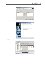
Page 355: ...System Upgrade 8 19 15 Check the disk you selected and click Next 16 Click Complete ...
Page 399: ...System Upgrade 8 63 Cable ties included with cabinet ...
Page 410: ...8 74 System Upgrade This page is intentionally left blank ...
Page 412: ...A 2 Specifications This page is intentionally left blank ...

