8-38 System Upgrade
DIMM
The DIMM (dual inline memory module) is installed to the DIMM socket in the CPU module on the
NEC Express5800/ft series.
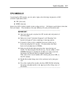
The CPU module board is equipped with six sockets. Two standard DIMMs are mounted in
DIMM#1 and #2 each. (The standard DIMM can be replaced with another DIMM.)
N8800-027F:
Two 128MB DIMMs
N8800-028F:
Two 256MB DIMMs
DIMMs should be installed to these sockets, starting from the lowest socket number.
TIPS:
The memory capacity can be increased up to 3 GB (four 512 MB
DIMMs).
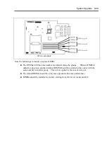
The DIMM connector may be identified as "group" in POST, NEC
ESMPRO, or error message/log of the Off-line Maintenance Utility.
The number displayed after the group corresponds to the connector
number shown in the figure below.
IMPORTANT:
The DIMM is extremely sensitive to static electricity. Make sure
to touch the metal frame of the server to discharge static electricity
from your body before handling the DIMM. Do not touch the
DIMM terminals or on-board parts with a bare hand or place the
DIMM directly on the desk. For static notes, see the section
"Anti-static Measures" described earlier.
Make sure to use the DIMM authorized by NEC. Installing a
third-party DIMM may cause a failure of the DIMM as well as the
server. Repair of the server due to failures or damage resulted
from installing such a board will be charged.
Before adding or removing DIMMs, power off the server and detach
the CPU module.
Make sure to read "Anti-static Measures" and "Preparing Your
System for Upgrade" before installing or removing options.
Summary of Contents for Express5800/320Lb FT Linux
Page 10: ...iv This page is intentionally left blank ...
Page 16: ...x This page is intentionally left blank ...
Page 19: ...Precautions for Use 1 3 Label A Label B Label C Label E Label D ...
Page 20: ...1 4 Precautions for Use Rack mount model Label B Label A Label C Label D ...
Page 21: ...Precautions for Use 1 5 Label D Label C Label B Label A ...
Page 22: ...1 6 Precautions for Use PCI CPU Modules PCI Module CPU Module Label A Label A Label A ...
Page 36: ...1 20 Precautions for Use This page is intentionally left blank ...
Page 44: ...2 8 General Description Front View inside Tower model Rack mount model ...
Page 70: ...2 34 General Description This page is intentionally left blank ...
Page 118: ...3 48 Setup This page is intentionally left blank ...
Page 162: ...4 44 System Configuration This page is intentionally left blank ...
Page 294: ...6 14 Maintenance This page is intentionally left blank ...
Page 336: ...7 42 Troubleshooting This page is intentionally left blank ...
Page 355: ...System Upgrade 8 19 15 Check the disk you selected and click Next 16 Click Complete ...
Page 399: ...System Upgrade 8 63 Cable ties included with cabinet ...
Page 410: ...8 74 System Upgrade This page is intentionally left blank ...
Page 412: ...A 2 Specifications This page is intentionally left blank ...

